
Communication device, communication system, and communication fault detection method
Patent Information
- Authority / Receiving Office
- US · United States
- Current Assignee / Owner
- Publication Date
- 2009-06-04
- Estimated Expiration
- Not applicable · inactive patent
Smart Images
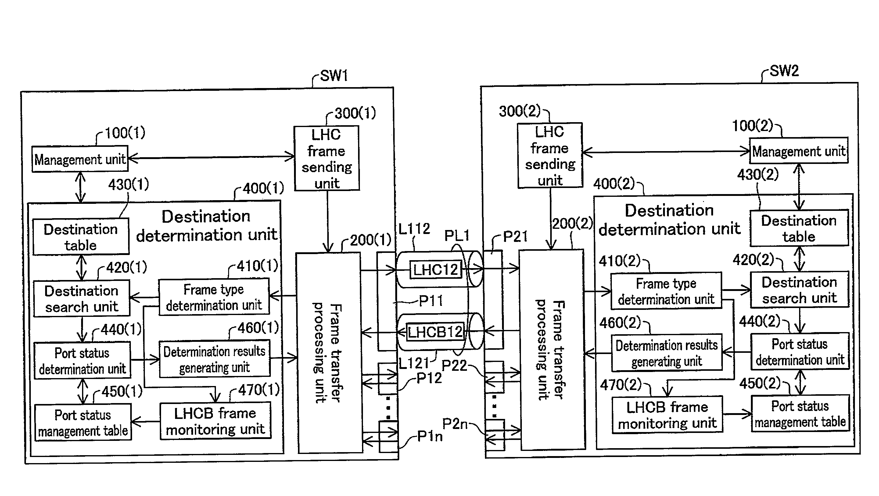
Figure 1 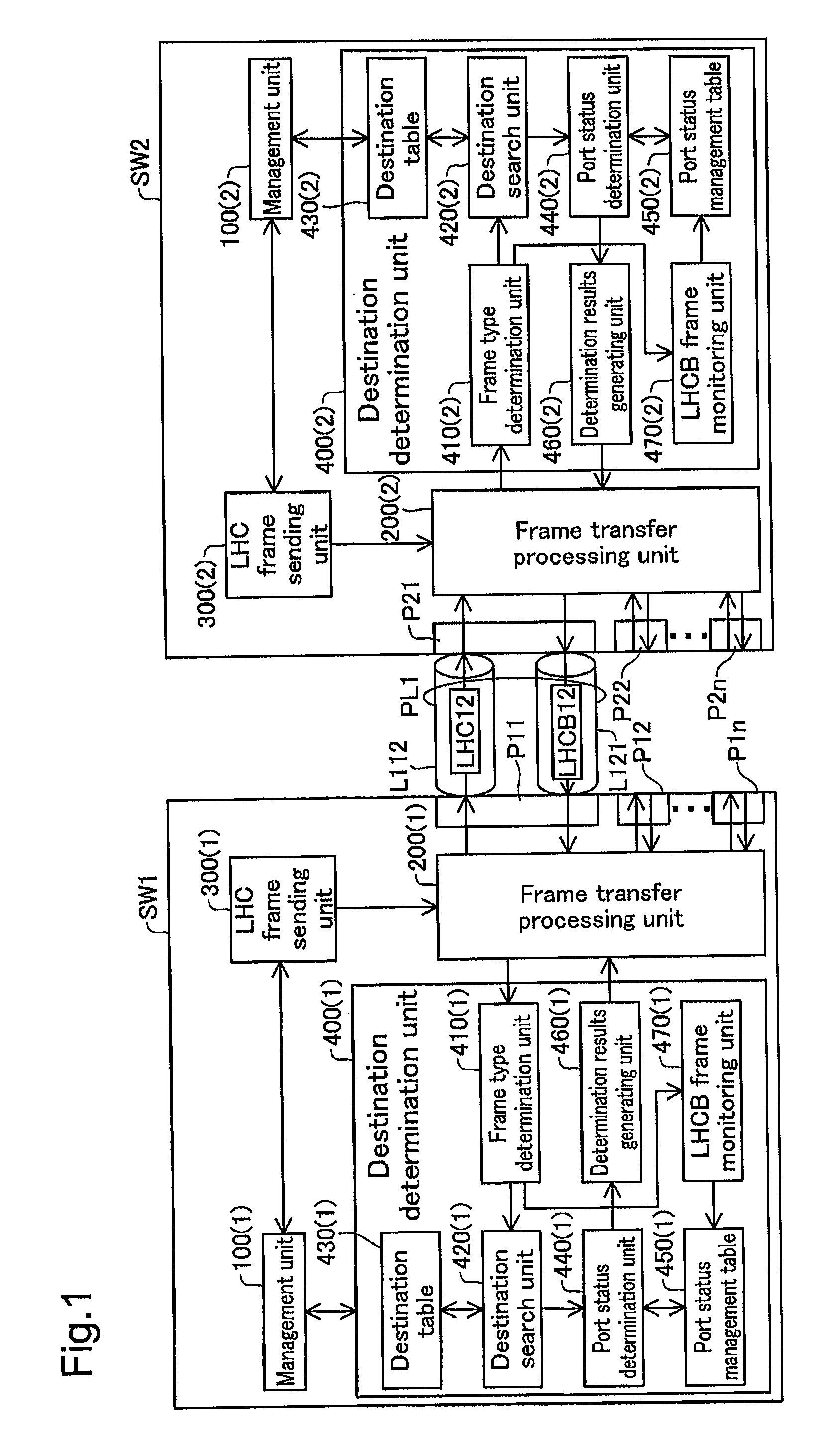
Figure 2 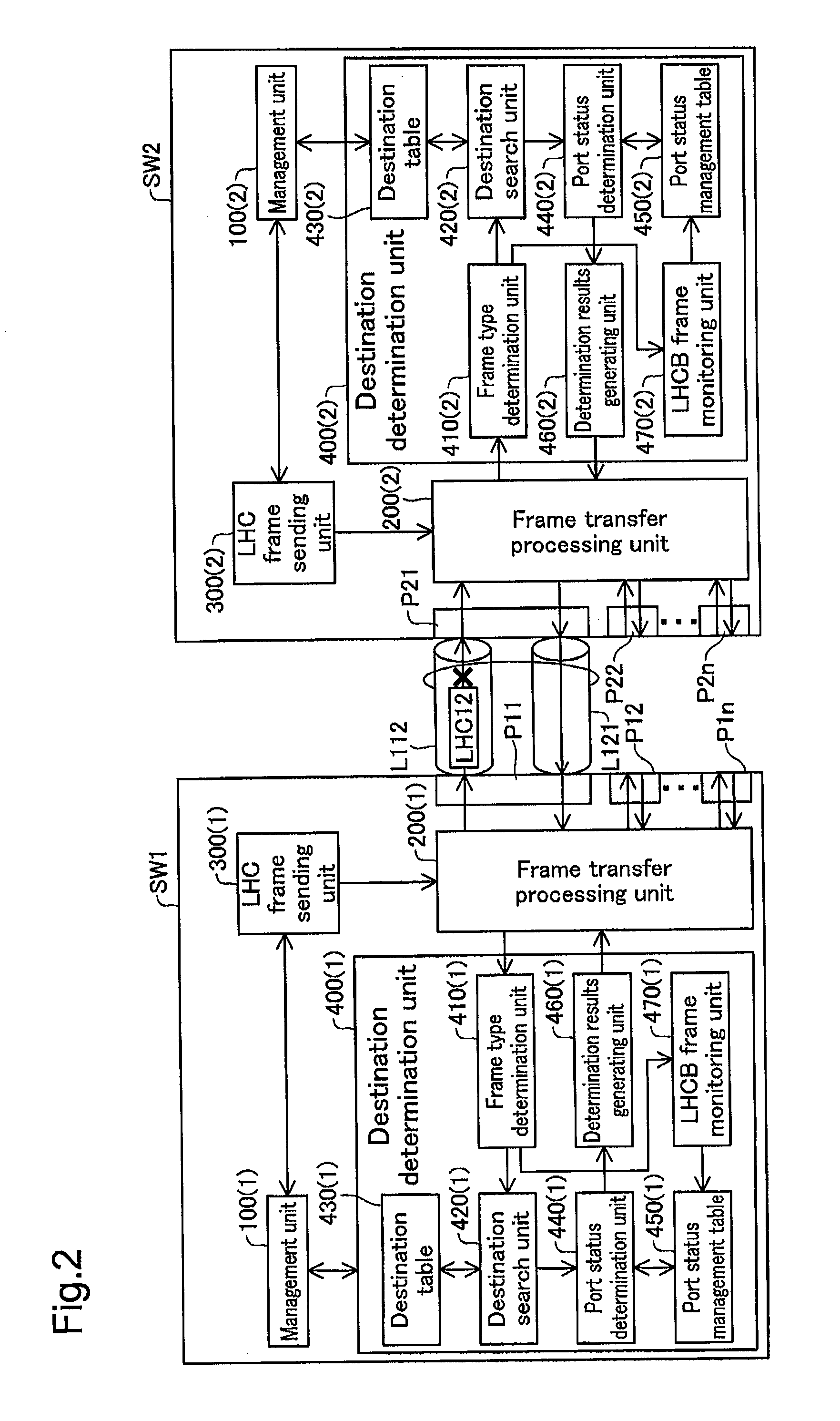
Figure 3
Abstract
Description
CROSS-REFERENCE TO RELATED APPLICATIONS
[0001] The present application claims the priority based on Japanese Patent Application No. 2007-308224 filed on Nov. 29, 2007, the disclosure of which is hereby incorporated by reference in its entirety.BACKGROUND OF THE INVENTION
[0002] 1. Field of the Invention
[0003] The present invention relates to a communication device, and particularly to a communication device for performing fault detection on a network.
[0004] 2. Description of the Related Art
[0005] The physical line of one port connecting two communication devices is constituted by two lines, which serve a bidirectional link between the two communication devices. There are cases when a fault occurs with one link of the two links (called “unidirectional link fault”). With the unidirectional link fault, one of the communication devices is possible to send messages but not to receive, while the other of the communication devices is possible to receive messages but not to send, whereby various t...
Examples
first embodiment
A. First Embodiment
[0053]FIG. 1 and FIG. 2 are block diagrams for describing the unidirectional link fault detection executed with the communication device as the first embodiment. FIG. 1 shows a case of a normal state when a fault has not occurred, and FIG. 2 shows a case of a fault occurrence state.
[0054]A switch SW1, which is the first communication device, has a plurality of ports P11 to P1n where n is an integer of 2 or greater. The first port P11 of the first switch SW1 is connected via the physical line PL1 to the first port P21 of the plurality of ports P21 to P2n provided in a switch SW2, which is the second communication device. The physical line PL1 is constituted by two links (bidirectional link), including a first link L112 on which are sent Ethernet® frames (hereafter simply called “frames”) from the first switch SW1 toward the second switch SW2, and a second link L121 on which frames are sent from the second switch SW2 to the first switch SW1. Note that to make the de...
second embodiment
B. Second Embodiment
[0111]FIG. 16 and FIG. 17 are block diagrams for explaining the unidirectional link fault detection executed with the communication device as the second embodiment, where FIG. 16 shows a case of a normal status when a fault has not occurred, and FIG. 17 shows a case of a fault occurrence state.
[0112]A switch SW1A, which is the first communication device, has a plurality of ports P11 to P1n where n is an integer of 2 or greater. The first switch SW1A is connected via the physical line PL1 connected to the first port P11 to the first port P21 of the plurality of ports P21 to P2n provided in a switch SW2A which is the second communication device. The physical line PL1 is constituted by two links (bidirectional link), including a first link L112 on which are sent Ethernet frames from the first switch SW1A toward the second switch SW2A, and a second link L121 on which frames are sent from the second switch SW2A to the first switch SW1A. Note that with the second embod...