
Rotary Solenoid
a solenoid and rotary technology, applied in the direction of dynamo-electric machines, electrical apparatus, magnetic bodies, etc., can solve the problems of high production cost, corresponding cost, and the need to produce each coil rather expensive, so as to achieve the effect of production
Patent Information
- Authority / Receiving Office
- US · United States
- Patent Type
- Applications(United States)
- Current Assignee / Owner
- Publication Date
- 2011-08-04
Smart Images
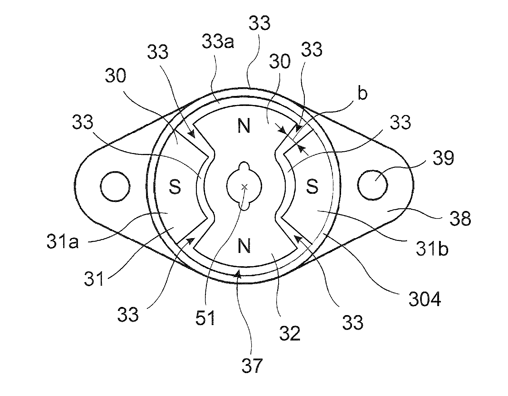
Figure 1 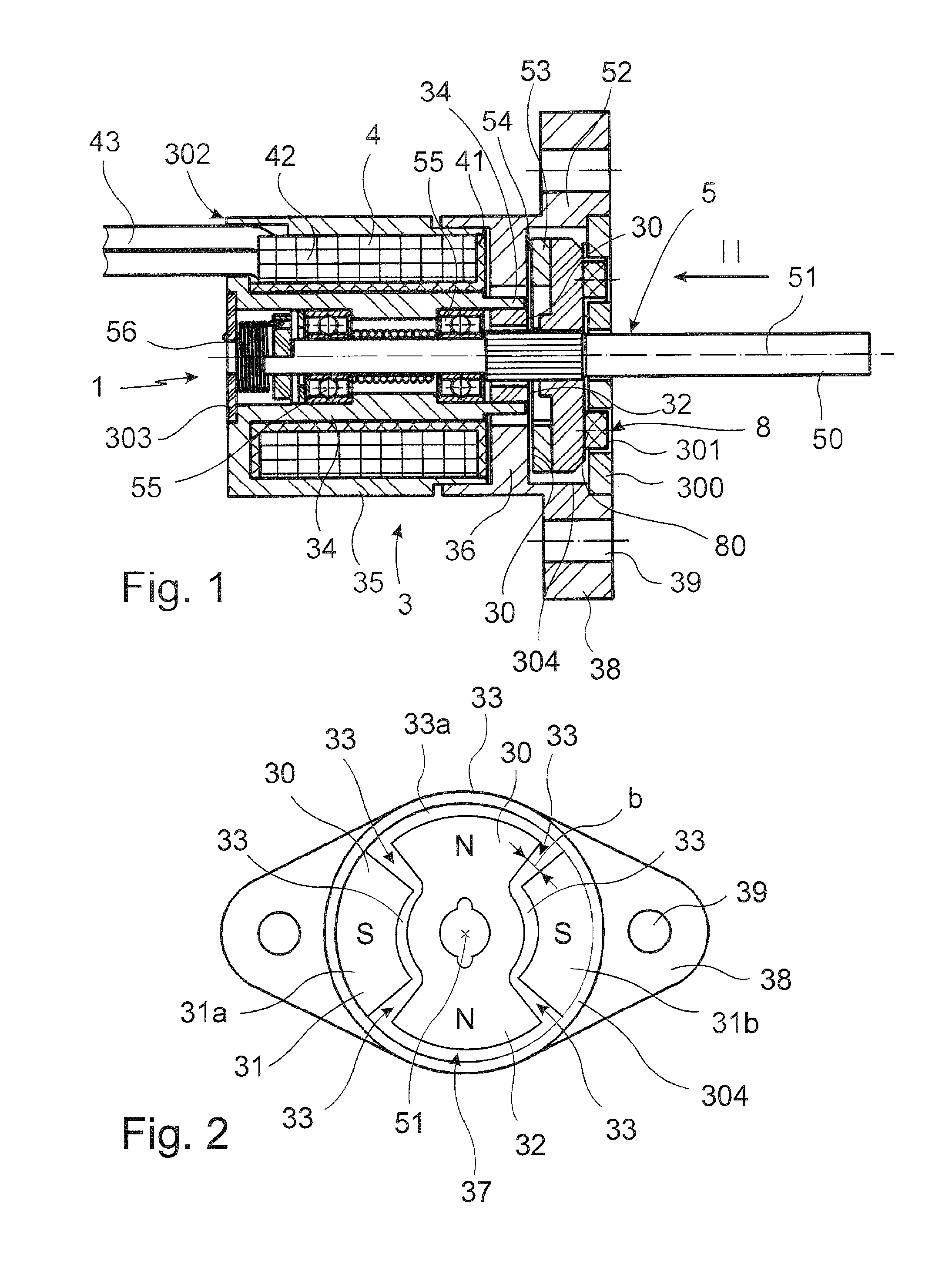
Figure 2 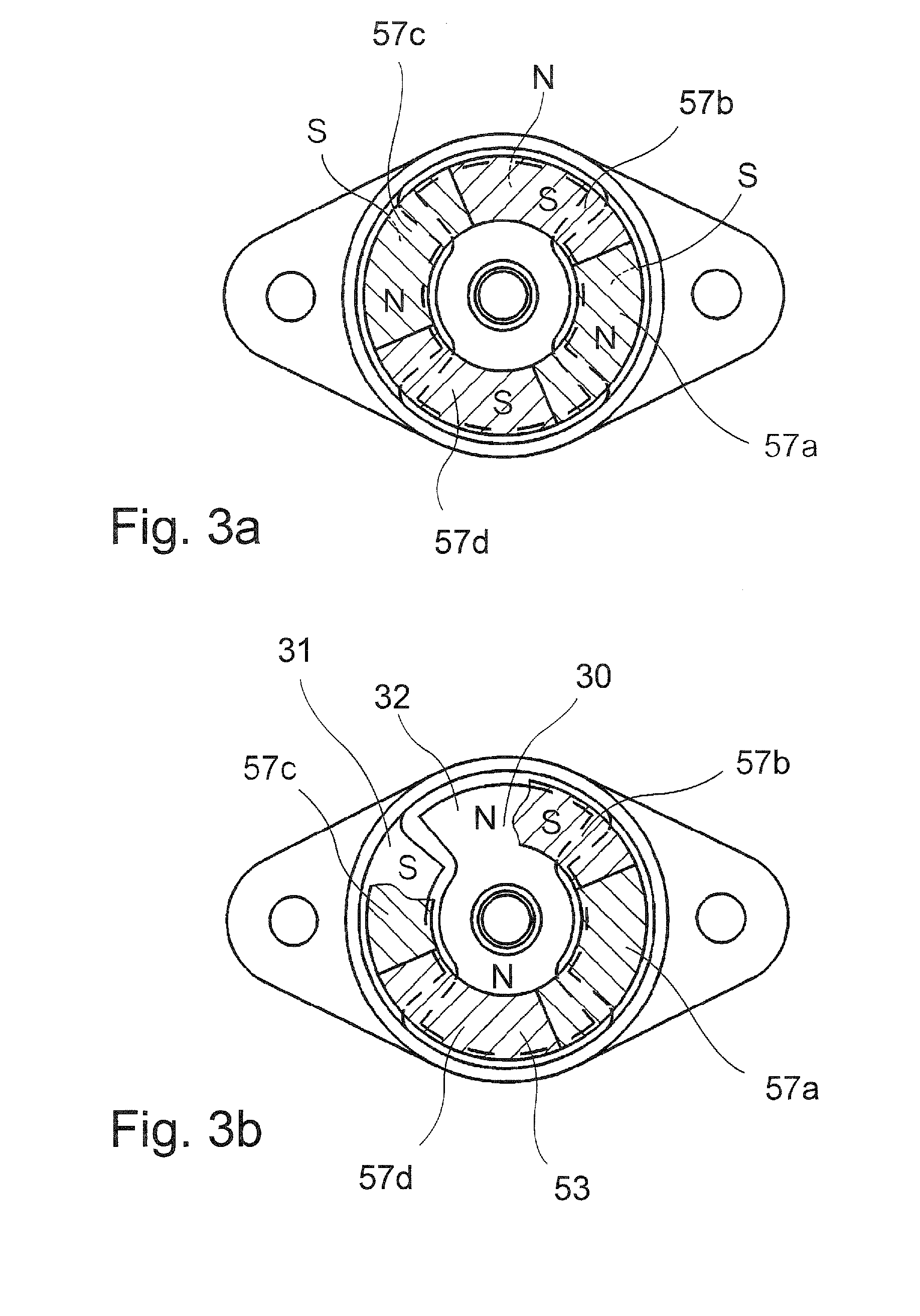
Figure 3
Abstract
Description
[0001] The invention refers to a Rotary Solenoid comprising a stator and a rotor rotatable around a rotational axis, wherein the rotor has a rotor shaft on which a rotor disc is arranged, and the rotor disc is polarized magnetically alternating, seen in the direction of the circumference, and the stator receives at least one coil that carries windings of electrically conducting wire, and between the coil and the rotor disc a pole face preferably arranged rectangular to the rotational axis is provided.BACKGROUND OF THE INVENTION
[0002] Rotary Solenoids of this type are drives basing on the electro magnetic principle where, instead of a longitudinal motion, the result is a rotary motion. Rotary Solenoids of this kind are known, for example, as rotary proportional solenoids carrying out a rotary motion proportional to the current flow because of the current flow through the windings.
[0003] In the state of the art it is known not to realize a magnetic field arrangement rotational symmetric ...
Examples
Embodiment Construction
[0043]In the figures identical or corresponding elements each are indicated by the same reference numbers, and therefore are not described anew, if not useful.
[0044]The Rotary Solenoid 1 according to the invention is shown schematically in a sectional view in FIG. 1. The Rotary Solenoid 1 comprises essentially a stator 3 and a rotor 5. The stator 3 receives the coil 4, the rotor 5 rotates around the rotational axis 51.
[0045]In the example shown here the stator 3 consists of two parts, namely the case part 35 and the lid part 36. The case part 35 is designed pot-like and receives the coil 4. At the same time, in particular the case part 35 acts as housing and terminates the Rotary Solenoid 1.
[0046]The outer shape of the case part 35 is here pot-like, wherein concentrically a center pole 34 is provided pin-like on which the coil form 41 of the coil 4 can be put. On the inside of the center pole 34 two pivot bearings 55 are provided somewhat spaced apart from each other with respect to...