
Device for measuring a fluid meniscus
a fluid meniscus and geometry technology, applied in the direction of resistance/reactance/impedence, electric/magnetic measuring arrangement, instruments, etc., can solve the problem of impeded determination of single capacitance by the interaction of auxiliary electrodes, and achieve the effect of accurate measurement of geometry
Patent Information
- Authority / Receiving Office
- US · United States
- Current Assignee / Owner
- Publication Date
- 2011-08-25
Smart Images
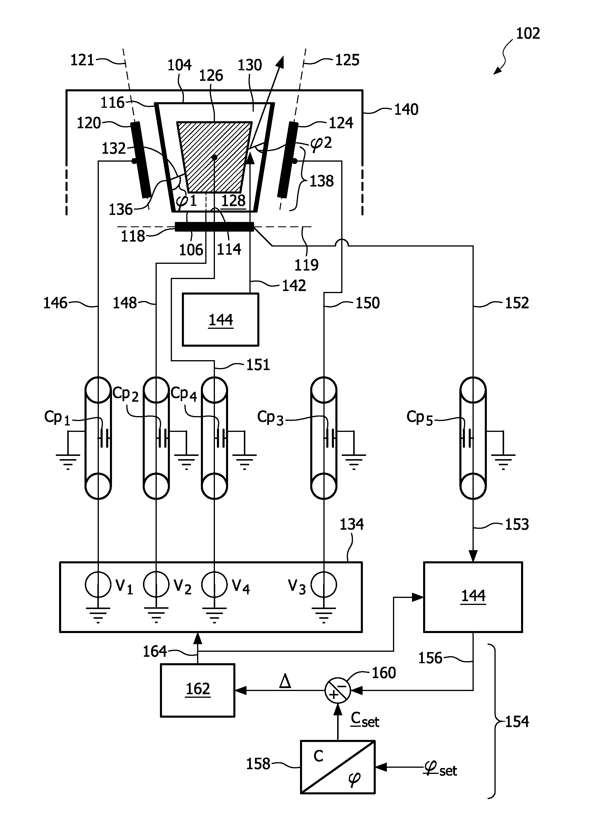
Figure 1 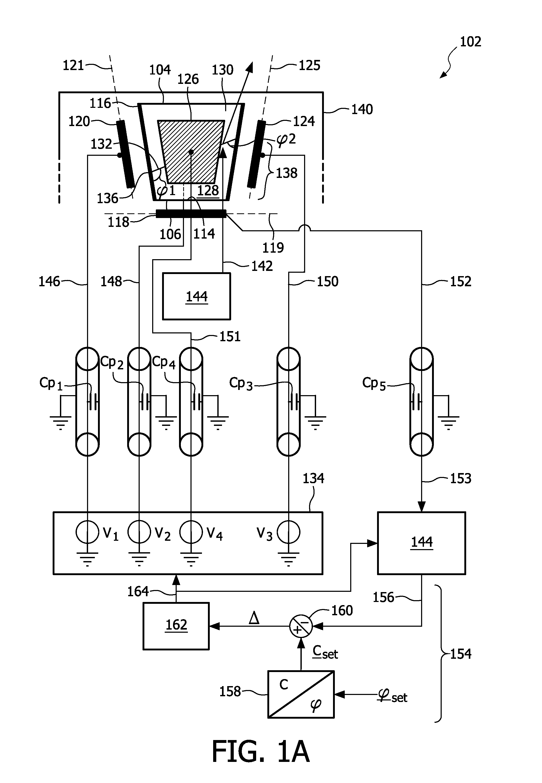
Figure 2 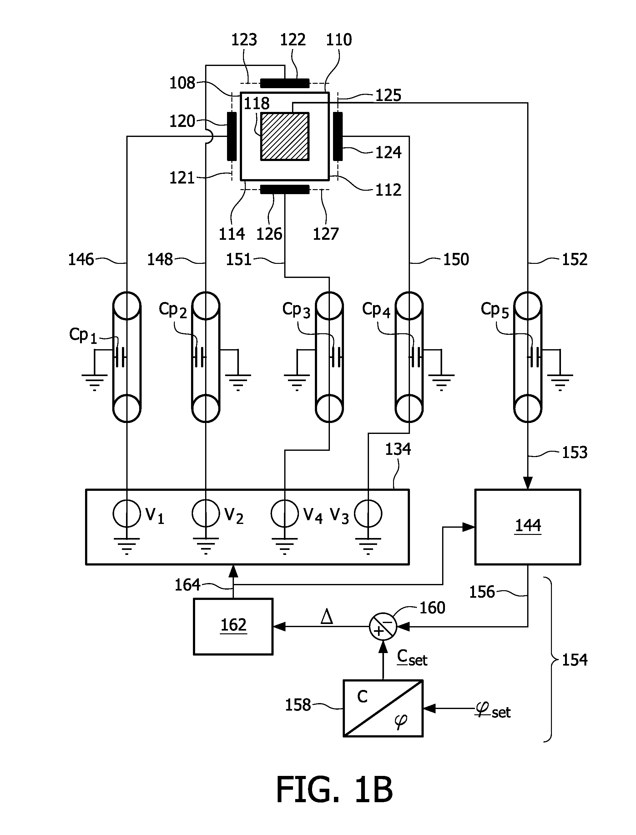
Figure 3
Abstract
Description
FIELD OF THE INVENTION
[0001] The invention relates to a device for measuring a geometry of a fluid meniscus.
[0002] The invention further relates to a catheter comprising such a device.
[0003] The invention further relates to a method for measuring a geometry of a fluid.BACKGROUND OF THE INVENTION
[0004] In WO 2006 / 035407 A1, a controllable optical lens system is disclosed. Said system comprises a lens having a chamber housing first and second fluids, wherein the interface between the fluids define a lens surface. The system further comprises an electrode arrangement comprising a first electrode and a second electrode for electrically controlling the shape of the lens surface, a feedback control loop for controlling the electrode arrangement based on a signal provided by a capacitance sensing arrangement, which capacitance sensing arrangement serves for measuring a capacitance between the first and second electrodes.
[0005] The techniques disclosed in WO2006 / 035407 A1 are less suitable for g...
Examples
first embodiment
[0029]the device according to the invention is depicted in FIG. 1A, FIG. 1B and FIG. 2. FIG. 1A depicts a cross section and a bottom view of a device 102 whereas a FIG. 1B shows a bottom view of said device. The device 102 comprises a fluid chamber 104, which fluid chamber 104 has a bottom 106 and a wall having wall parts 108, 110, 112 and 114, see also FIG. 1B. The wall parts 108, 110, 112 and 114 are provided with an insulating layer 116 for preventing shortcuts, see FIG. 1A. In alternative embodiments the fluid chamber may have a conical or a cylindrical wall, or any other suitable wall. The device 102 further comprises a main electrowetting electrode 118, which is attached to the bottom 106 in this particular embodiment, and auxiliary electrowetting electrodes 120, 122, 124 and 126, see FIG. 1B, which partially surround the fluid chamber 104 and are attached to the wall parts 108, 110, 112 and 114, respectively. In this particular example, the main plane 119 and the auxiliary pl...
second embodiment
[0041]the invention is depicted in FIG. 3A, FIG. 3B and FIG. 4. FIG. 3A depicts a cross section of a device 302 whereas FIG. 3B displays a bottom view of said device 302. The device 302 comprises a fluid chamber 304, the fluid chamber 304 having a top 306 and a wall having wall parts 308, 310, 312 and 314, see FIG. 3B. The wall parts 308, 310, 312 and 314 are provided with an insulating layer 316 for preventing shortcuts, see FIG. 3A. In alternative embodiments the fluid chamber 304 may have a conical or a cylindrical wall, or any other suitable wall. The device 302 comprises a grounded main electrowetting electrode 318 attached to the top 306. In this particular example, the device 302 comprises two auxiliary electrowetting electrodes 320 and 322, which partially surround the fluid chamber 304 and which are attached to the wall parts 308 and 312, respectively.
[0042]As indicated in FIG. 3A, the fluid chamber 304 comprises a first fluid 324 and a second fluid 326, which first and sec...