
Control device
a control device and control technology, applied in the direction of electric devices, process and machine control, instruments, etc., can solve the problems of deteriorating fuel efficiency and dissatisfaction of drivers, and achieve the effect of suppressing the deterioration of fuel efficiency and small reduction of energy efficiency
Patent Information
- Authority / Receiving Office
- US · United States
- Patent Type
- Applications(United States)
- Current Assignee / Owner
- Publication Date
- 2012-03-29
Smart Images
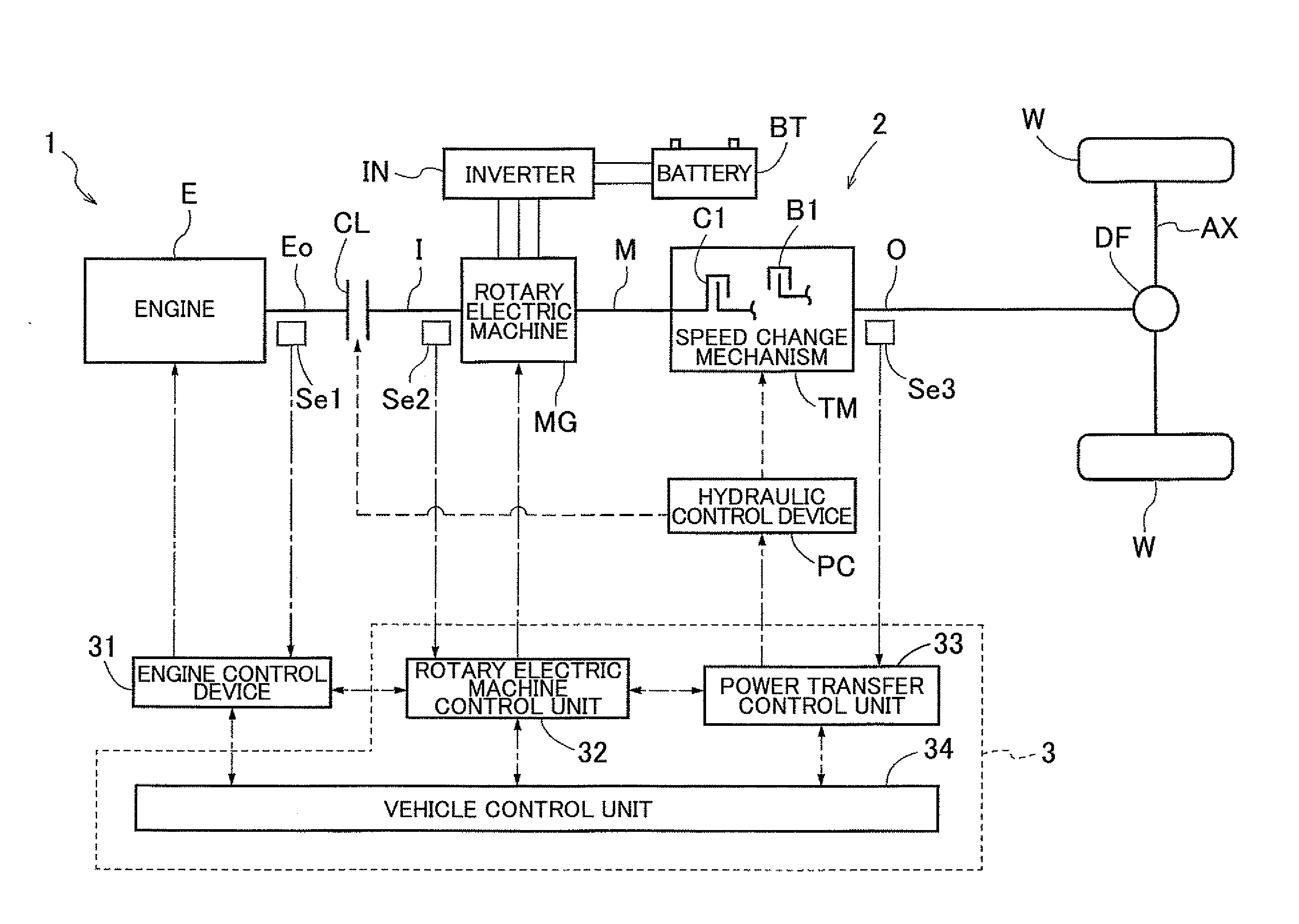
Figure 1 
Figure 2 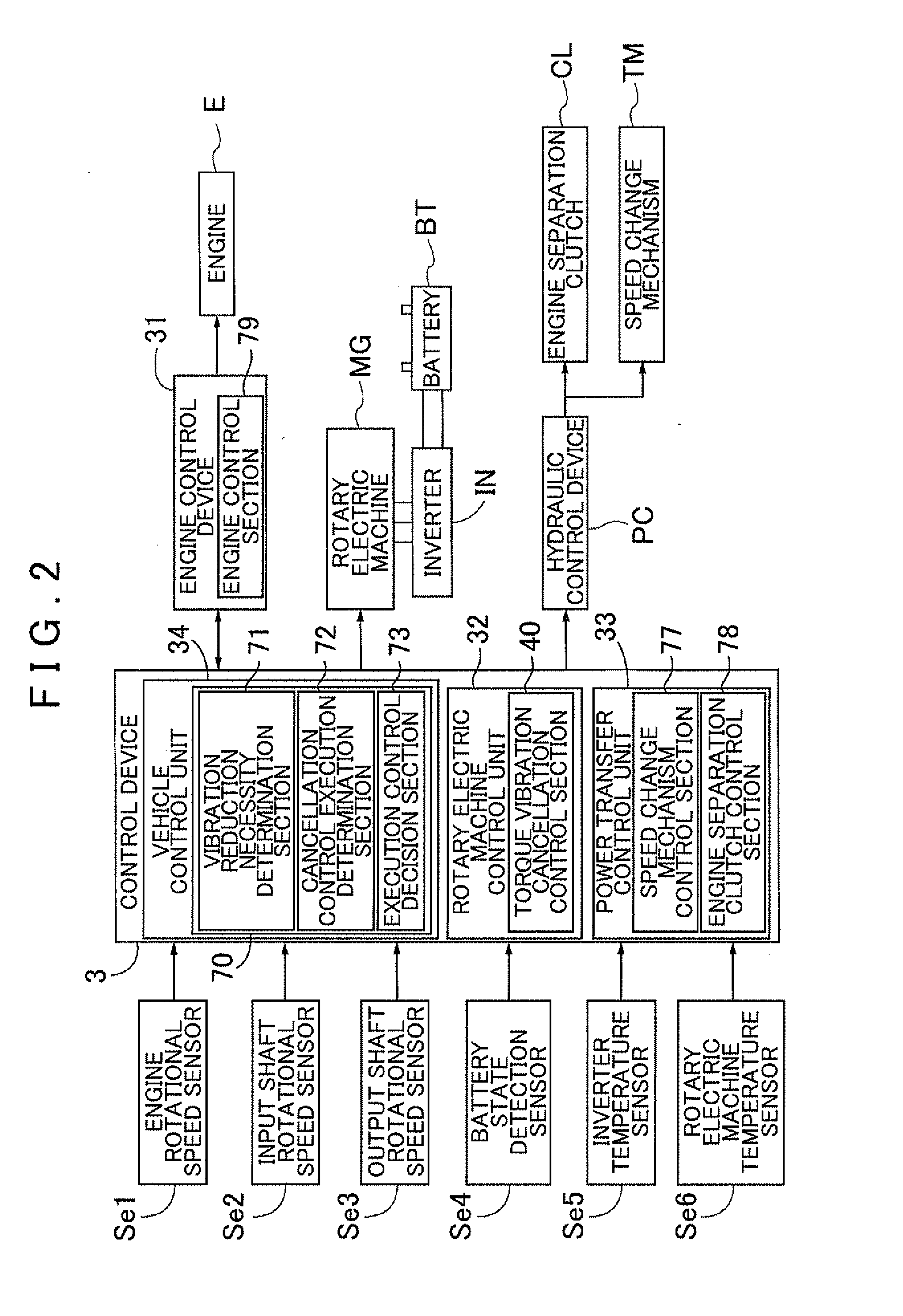
Figure 3
Abstract
Description
INCORPORATION BY REFERENCE
[0001] The disclosure of Japanese Patent Application No. 2010-219933 filed on Sep. 29, 2010 including the specification, drawings and abstract is incorporated herein by reference in its entirety.BACKGROUND OF THE INVENTION
[0002] The present invention relates to a control device that controls a vehicle drive device in which a rotary electric machine is provided on a power transfer path connecting between an input member drivably coupled to an internal combustion engine and an output member drivably coupled to wheels.DESCRIPTION OF THE RELATED ART
[0003] A drive range of an internal combustion engine includes a high-vibration range in which torque vibration output from the internal combustion engine is significant. In the high-vibration range, the torque vibration may be transferred to a drive device for a vehicle to produce a muffled sound, causing a discomfort to a driver. Japanese Patent Application Publication No. 2010-138751 mentioned below, for example, dis...
Examples
Embodiment Construction
[0037]A control device 3 according to an embodiment of the present invention will be described with reference to the drawings. FIG. 1 is a schematic diagram showing a schematic configuration of a vehicle drive device 1 according to the embodiment. As shown in the drawing, a vehicle incorporating the vehicle drive device 1 is a hybrid vehicle including an engine E, which is an internal combustion engine, and a rotary electric machine MG each serving as a drive force source for the vehicle. In the drawing, the solid lines each indicate a drive force transfer path, the broken lines each indicate a working oil supply path, and the dash-dotted lines each indicate a signal transfer path. In the embodiment, the control device 3 is a device that controls the vehicle drive device 1 in which the rotary electric machine MG is provided on a power transfer path 2 connecting between an input shaft I drivably coupled to the engine E and an output shaft O drivably coupled to wheels W. In the embodi...