
Heat generation inhibiting circuit for exciting coil in relay
a heat generation and inhibiting circuit technology, applied in electromagnetic relays, electrical apparatus, relays, etc., can solve the problems of increasing the size of the pcb substrate, generating power loss, and difficult mounting of the relay circuit on the pcb substrate, so as to reduce the required space, reduce the voltage applied to the exciting coil, and reduce the amount of heat generation
Patent Information
- Authority / Receiving Office
- US · United States
- Patent Type
- Applications(United States)
- Current Assignee / Owner
- Publication Date
- 2012-06-28
- Estimated Expiration
- Not applicable · inactive patent
Smart Images
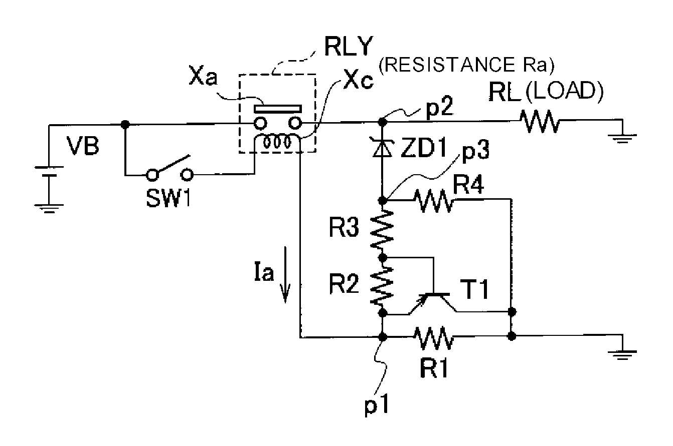
Figure 1 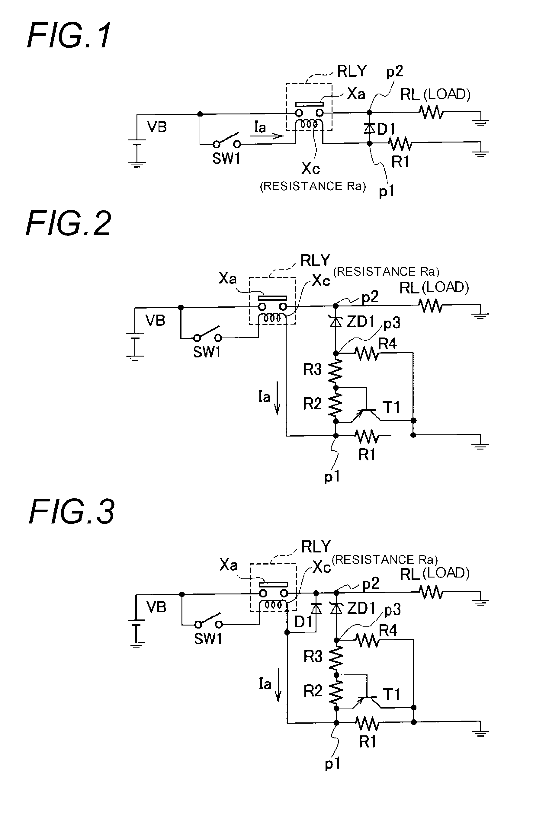
Figure 2 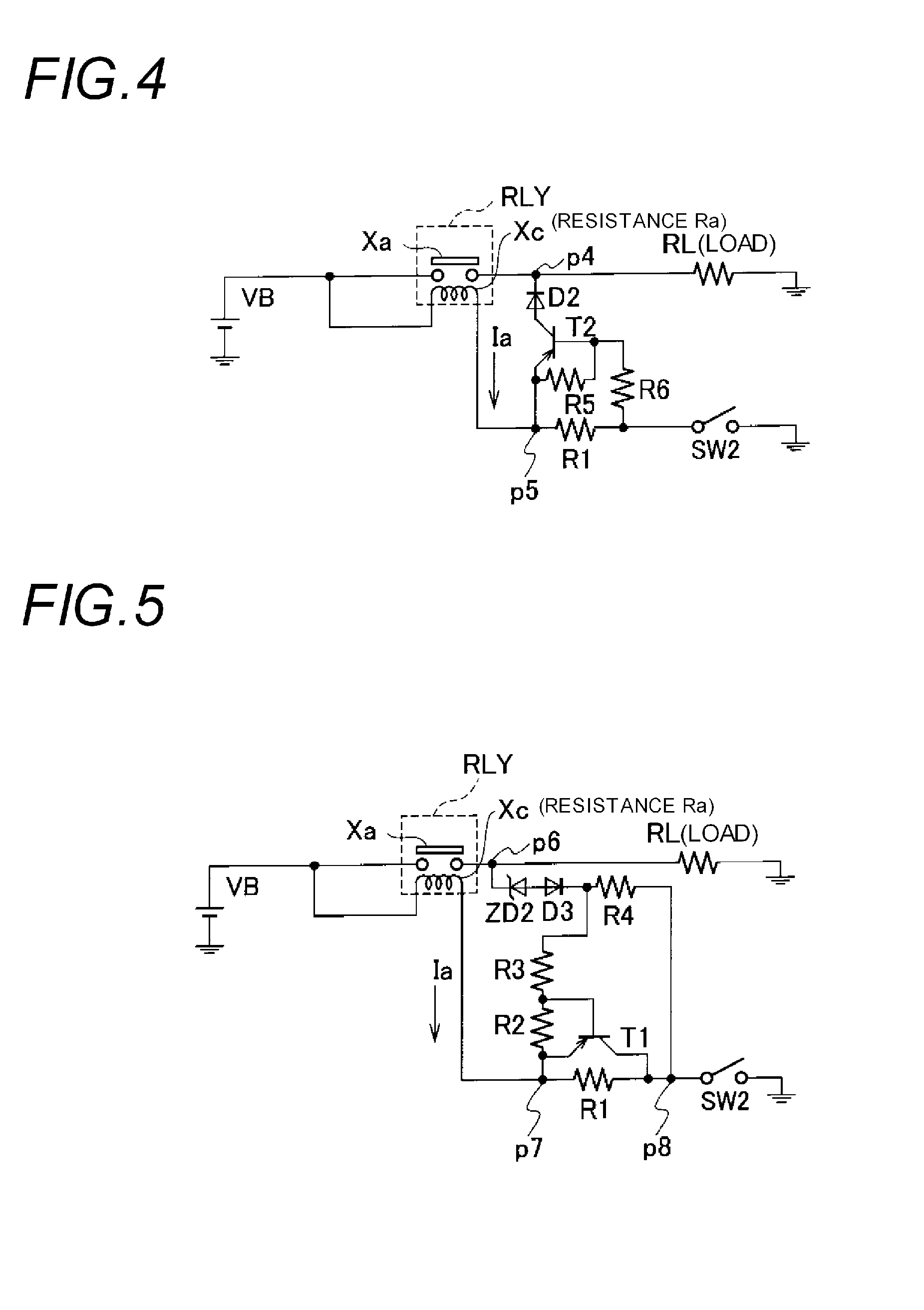
Figure 3
Abstract
Description
TECHNICAL FIELD
[0001] The present invention relates to a heat generation inhibiting circuit for inhibiting the heat generation of an exciting coil provided in a relay circuit.BACKGROUND ART
[0002] For example, a relay circuit for controlling the driving and stop of various kinds of loads such as a lamp and a motor mounted on a vehicle is used in a state of being mounted on a PCB substrate. In such the relay circuit, power loss is generated when an exciting coil for exciting a relay contact is supplied with current. The power loss is converted into heat energy to increase the temperature of the PCB substrate. In the case of using the PCB substrate within an engine room of a high ambient temperature, since such the use causes the temperature of various devices mounted on the PCB substrate to exceed the allowable temperature thereof, it becomes difficult to mount may relay circuits on the PCB substrate. In other words, since the number of the relay circuits capable of being mounted on the...
Examples
first embodiment
[0052]FIG. 1 is a circuit diagram showing the configuration of a load driving circuit on which a heat generation inhibiting circuit according to the first embodiment of this invention is mounted. As shown in FIG. 1, the load driving circuit includes a load RL such a lamp and a motor mounted on a vehicle, for example, and a DC power supply VB (for example, a battery, hereinafter abbreviated as “power supply VB”), and a relay circuit RLY is provided between the power supply VB and the load RL. The output voltage of the power supply VB is shown by the same symbol VB. This output voltage is 14 volt, for example.
[0053]The relay circuit RLY includes a normally-opened relay contact Xa and an exciting coil Xc. The one end of the relay contact Xa is connected to the positive electrode terminal of the power supply VB and the other end thereof is grounded via the load RL. The resistance value of the exciting coil Xc is Ra. The one end of the exciting coil Xc is connected to the positive electr...
second embodiment
Modified Example of Second Embodiment
[0076]Next, the heat generation inhibiting circuit according to the modified example of the second embodiment will be explained. FIG. 3 is a circuit diagram showing the configuration of a load driving circuit on which the heat generation inhibiting circuit according to the modified example is mounted. As shown in FIG. 3, this load driving circuit differs from the circuit shown in FIG. 2 in a point that the diode D1 is provided. That is, the diode D1 is provided in a manner that the anode thereof is connected to the connection point p1 between the exciting coil Xc and the resistor R1 and the cathode thereof is connected to the connection point p2 between the relay contact Xa and the load RL.
[0077]In the heat generation inhibiting circuit thus configured, during a period that the relay contact Xa is opened after the switch SW1 is turned on, since the exciting current Ia flowing into the exciting coil Xc flows from the diode D1 to the ground via the...
third embodiment
[0078]Next, the third embodiment of this invention will be explained. FIG. 4 is a circuit diagram showing the configuration of a load driving circuit on which the heat generation inhibiting circuit according to the third embodiment of this invention is mounted. As shown in FIG. 4, this load driving circuit includes the load RL such a lamp and a motor and the power supply VB (for example, a battery), and the relay circuit RLY is provided between the power supply VB and the load RL.
[0079]The relay circuit RLY includes the normally-opened relay contact Xa and the exciting coil Xc. The one end of the relay contact Xa is connected to the positive electrode terminal of the power supply VB and the other end thereof is grounded via the load RL. The one end of the exciting coil Xc is connected to the positive electrode terminal of the power supply VB and the other end thereof is grounded via the resistor R1 (first resistor) and a switch SW2 (switch unit). That is, the third embodiment differ...