
Pouring nozzle and assembly of such a pouring nozzle with an inner nozzle
a technology of pouring nozzle and inner nozzle, which is applied in the field of pouring nozzle, can solve the problems of nozzle not being used for continuous casting of molten steel, affecting the flow of steel, and raising a serious security concern, so as to achieve the effect of reducing the disturbance of the flow of steel
Patent Information
- Authority / Receiving Office
- US · United States
- Patent Type
- Applications(United States)
- Current Assignee / Owner
- Publication Date
- 2012-08-23
- Estimated Expiration
- Not applicable · inactive patent
Smart Images
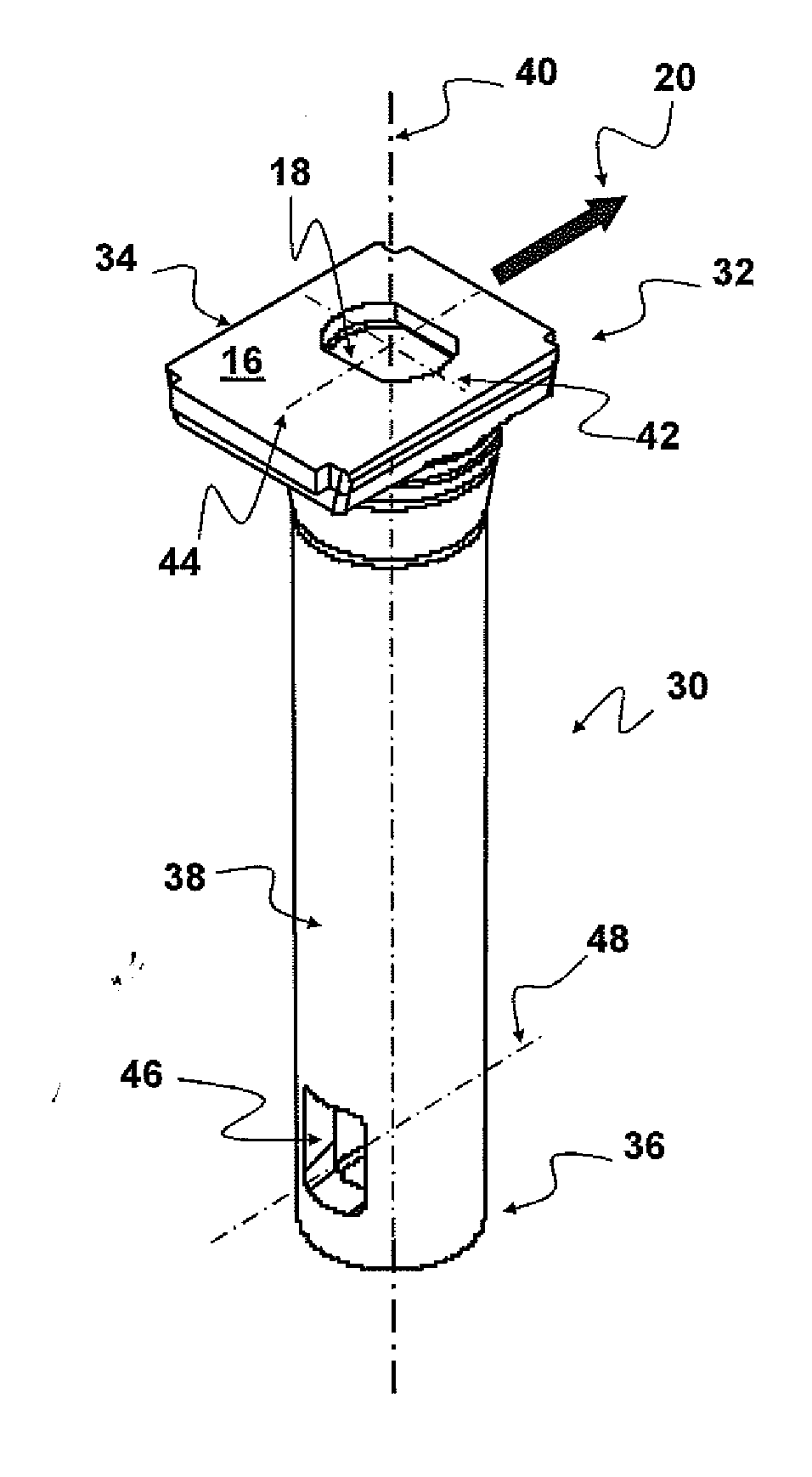
Figure 1 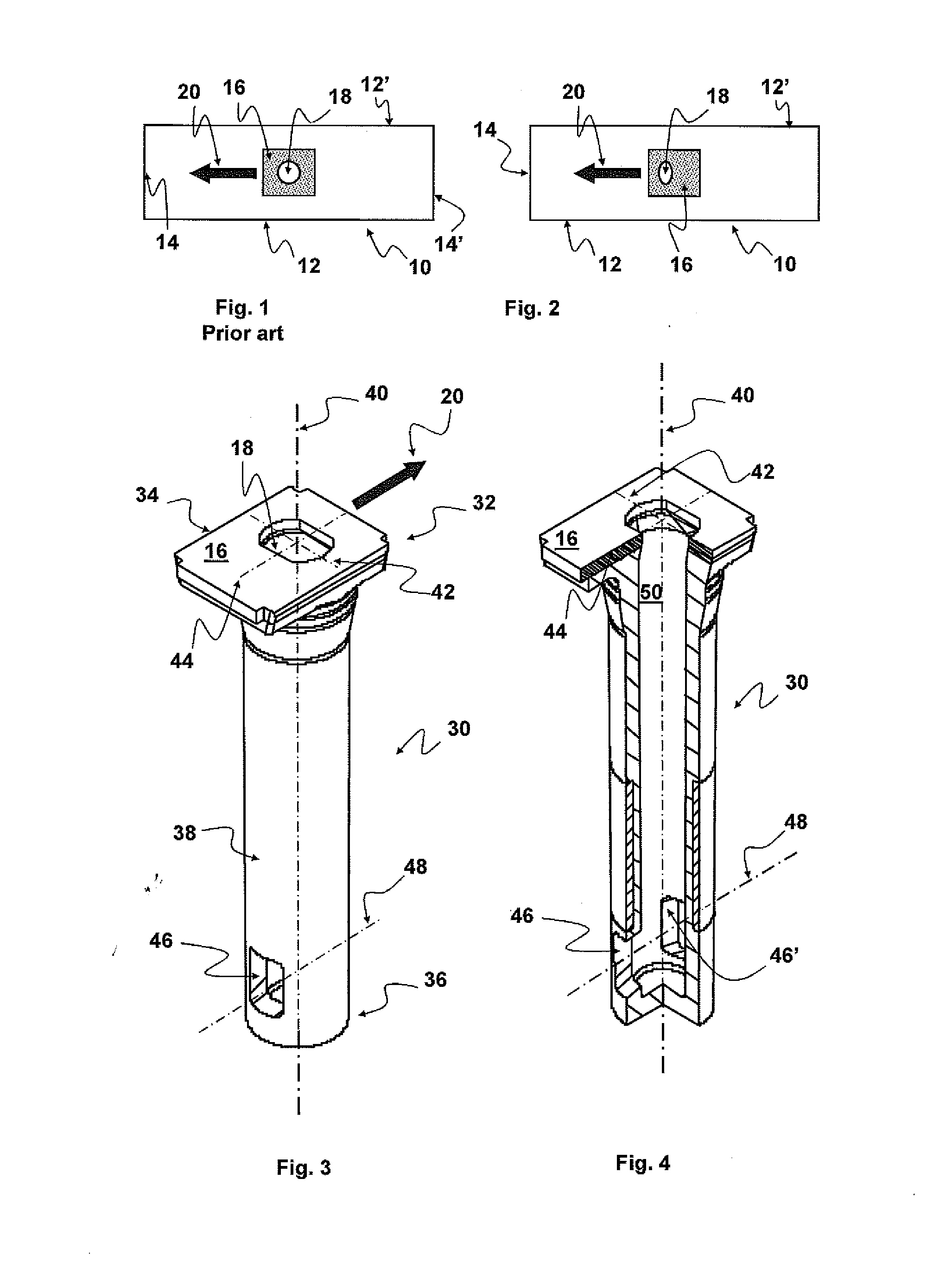
Figure 2
Abstract
Description
BACKGROUND OF THE INVENTION
[0001] (1) Field of the Invention
[0002] The present invention relates to a refractory element used for the continuous casting of molten steel from an upstream metallurgical vessel to a downstream metallurgical vessel.
[0003] According to a particular embodiment of the invention, the nozzle is used for casting molten steel from a distribution tank (sometimes also called a tundish) to a casting mould or ingot mould (sometimes also called a coquille).
[0004] (2) Description of Related Art
[0005] In the continuous casting of steel from the tundish to an ingot mould, a pouring nozzle is used to protect the liquid steel from chemical attacks from the surrounding atmosphere and to isolate it thermally during its transfer from the upstream vessel to the downstream vessel. These nozzles, roughly cylindrical in shape, consist of a single piece having an upstream end possessing a generally tapered inlet disposed in the vicinity of the bottom of the upstream vessel. These noz...
Examples
Embodiment Construction
[0031]An ingot mould 20, roughly rectangular in shape, having two long sides 12, 12′ and two small sides 14, 14′, can be seen schematically in FIGS. 1 and 2. At the centre of the ingot mould a pouring nozzle seen from above is shown, only the top surface 16 of which provided with a pouring orifice 18 can be seen. The details of the supplying and exchanging device are not visible in these figures. The direction 20 of sliding of the pouring nozzle in the nozzle supplying and exchanging device are also shown in each ingot mould. It will be noted that the discharge orifices of the pouring nozzle shown in FIGS. 1 and 2 are aligned in a direction parallel to the direction of sliding 20. Whereas the pouring orifice 18 of the nozzle known from the prior art (FIG. 1) is circular and centred with respect to the top surface 16, the pouring orifice 18 of the pouring nozzle according to the invention (FIG. 2) has an oblong shape. The orifice is elongate in a direction perpendicular to the direct...