
Method for determining a trigger level
a trigger level and level technology, applied in the field of determining the trigger level, can solve the problems of improper method and output jitter, and achieve the effect of reducing output jitter
Patent Information
- Authority / Receiving Office
- US · United States
- Current Assignee / Owner
- Publication Date
- 2013-10-17
- Estimated Expiration
- Not applicable · inactive patent
Smart Images
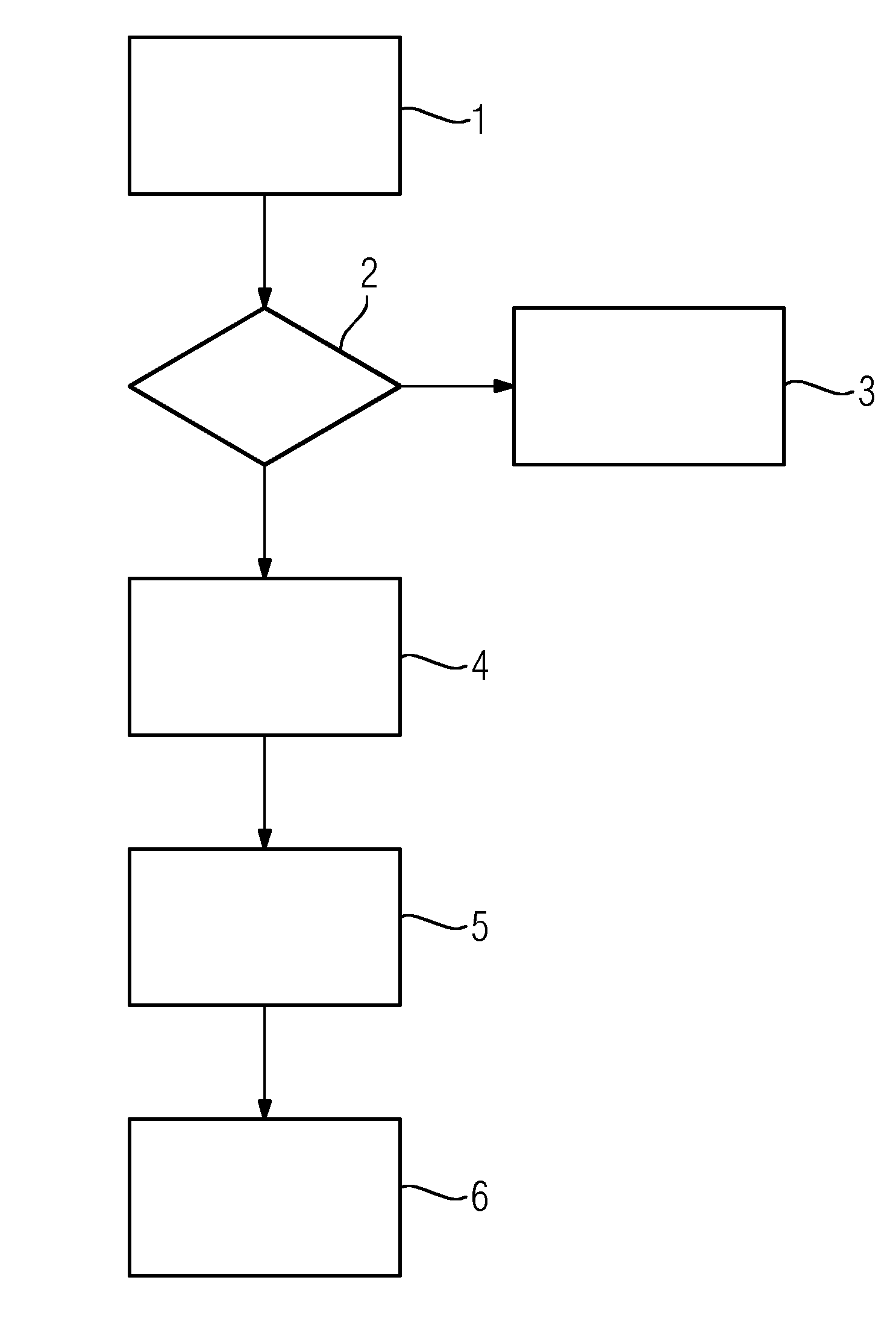
Figure 1 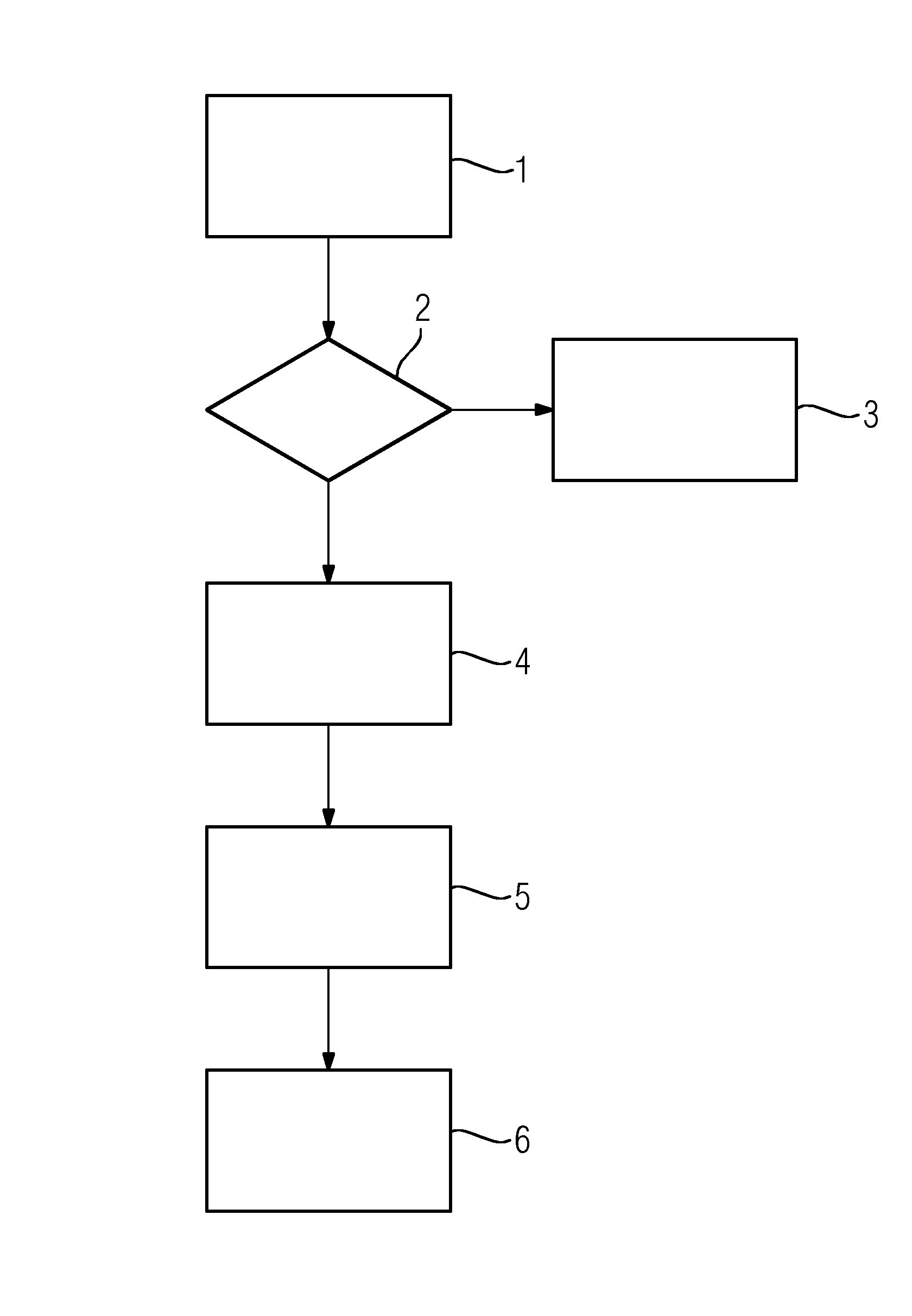
Figure 2 
Figure 3
Abstract
Description
CROSS REFERENCE TO RELATED APPLICATIONS
[0001] The present application claims priority to European Patent Office application No. 12163978.5 EP filed Apr. 12, 2012, the entire content of which is hereby incorporated herein by reference.FIELD OF INVENTION
[0002] The invention concerns a method for determining a trigger level for a periodic analog signal in a digital signal processing system.BACKGROUND OF INVENTION
[0003] Digital signal processing (DSP) is concerned with the representation of discrete time, discrete frequency, or other discrete domain signals by a sequence of numbers or symbols and the processing of these signals. The goal of DSP is usually to measure, filter and / or compress continuous real-world analog signals. The first step is usually to convert the signal from an analog to a digital form, by sampling and then digitizing it using an analog-to-digital converter (ADC), which turns the analog signal into a stream of numbers.
[0004] The main applications of DSP are audio signal...
Examples
Embodiment Construction
[0024]The method according to the embodiment of the FIGURE requires the following parameters:[0025]Trigger timeout value, T, from which a measurement update time can be calculated[0026]“Low voltage” value[0027]Minimum and maximum “safe area” limits, L1 and L2[0028]Trigger slope direction, bRisingDirection[0029]Number of possible trigger levels to be examined, N
[0030]The timeout value T is a time interval within which the input signal makes at least one period. Safe area limits are limit numbers given in percent. If the interval between the minimum and maximum value of input signal is 0-100%, then minimum and maximum safe area numbers select a smaller interval in which the optimum trigger level can be selected. Trigger slope direction tells, if the trigger level to be determined relates to rising edge (bRisingDirection=TRUE) or falling edge (bRisingDirection=FALSE).
[0031]The method consists of the following states:[0032]STATE1: Measuring 1 the minimum and maximum values of the analog...