
Internal Heat Exchanger for an Air Conditioning System
a heat exchanger and air conditioning technology, applied in the direction of heat exchange apparatus, tubular elements, stationary tubular conduit assemblies, etc., can solve the problems of increasing the heat exchange capacity maintaining the overall length of the heat exchanger at the same time, and achieve the effect of preventing leakag
Patent Information
- Authority / Receiving Office
- US · United States
- Patent Type
- Applications(United States)
- Current Assignee / Owner
- Publication Date
- 2014-06-05
- Estimated Expiration
- Not applicable · inactive patent
Smart Images
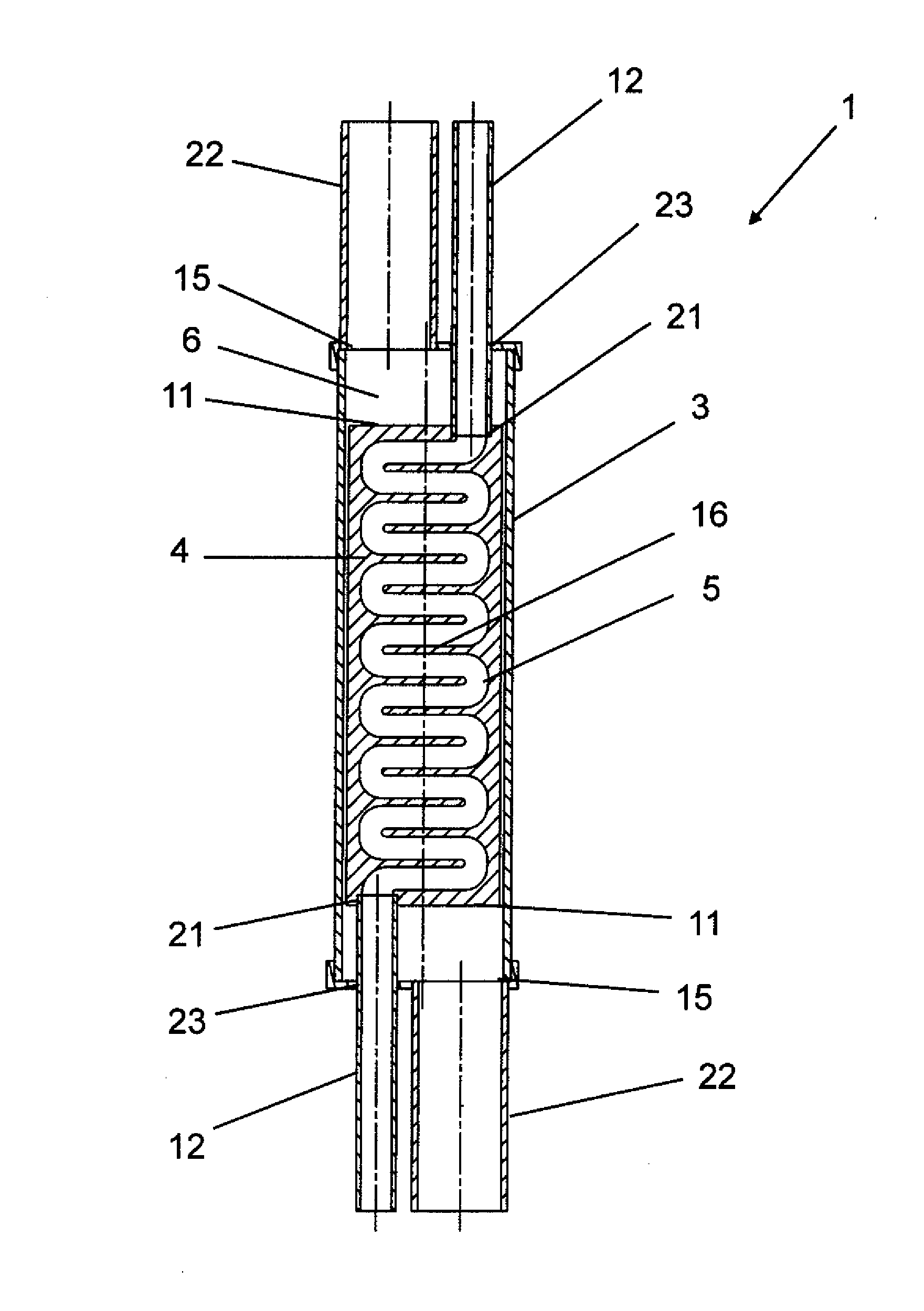
Figure 1 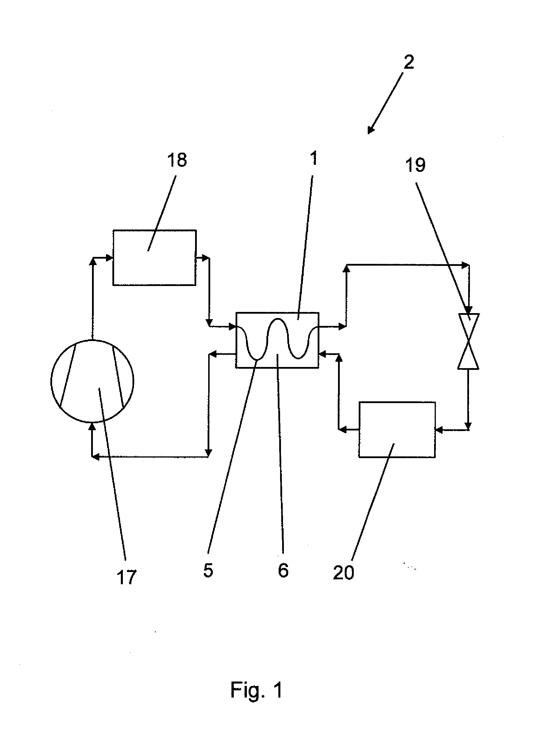
Figure 2 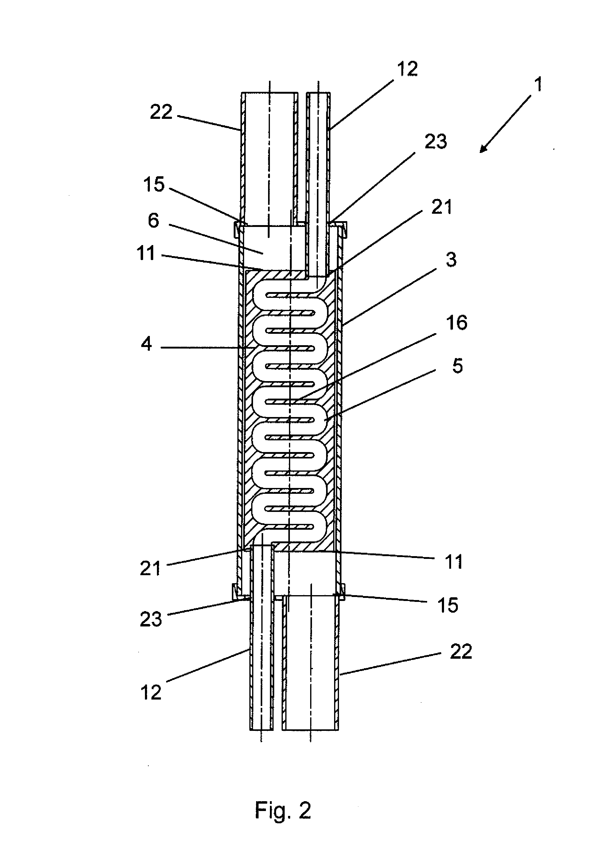
Figure 3
Abstract
Description
CROSS-REFERENCE TO RELATED APPLICATION
[0001] This application claims priority pursuant to Title 35 USC §119(e) to U.S. Provisional Patent Application No. 61 / 729,875, filed Nov. 26, 2012, entitled “Internal Heat Exchanger for an Air Conditioning System,” the entire specification and drawings of which are hereby incorporated by reference herein as if fully set forth.BACKGROUND
[0002] The invention relates to an internal heat exchanger for an air conditioning system, comprising an outer tube and a line structure arranged inside the outer tube, wherein the line structure includes a first flow channel, and wherein a second flow channel is formed between the outer tube and the line structure.
[0003] Such an internal heat exchanger is known from DE 10 2007 015 186 A1. An internal heat exchanger integrated into the coolant circuit of an air conditioning system makes it possible to increase the efficiency of an air conditioning system by transferring the heat of the coolant from its high-pressure...
Examples
Embodiment Construction
[0027]FIG. 1 presents a schematic view of the air conditioning circuit of a mobile air conditioning system 2, in particular the air conditioning system of a vehicle. The air conditioning system consists of a closed circuit piping arrangement between system components, in which a coolant circulates. The coolant is compressed by a compressor 17, and flows to a condenser 18, where the coolant is liquefied. After exiting the condenser, the coolant is liquid, and exhibits a temperature of 30° C. to 50° C. (Centigrade) at a pressure of 7 bar to 15 bar (Barometers). The liquefied coolant is now supplied to the first flow channel 5 of internal heat exchanger 1 according to the invention, where the coolant exiting the condenser 18 releases heat to the gaseous coolant exiting the evaporator 20 passes through the second flow channel 6. The liquid coolant then streams into the expansion valve 19, where the coolant pressure is reduced. The coolant absorbs heat in the evaporator 20, wherein it is...