
Sizing of a defect using phased array system
a phased array and defect technology, applied in the direction of mechanical measurement arrangements, mechanical roughness/irregularity measurements, instruments, etc., can solve the problems of completely manual process, heavy dependence on user interaction or operation, and rather slow process, etc., to achieve the effect of sizing a d
Patent Information
- Authority / Receiving Office
- US · United States
- Patent Type
- Applications(United States)
- Current Assignee / Owner
- Publication Date
- 2014-08-21
Smart Images
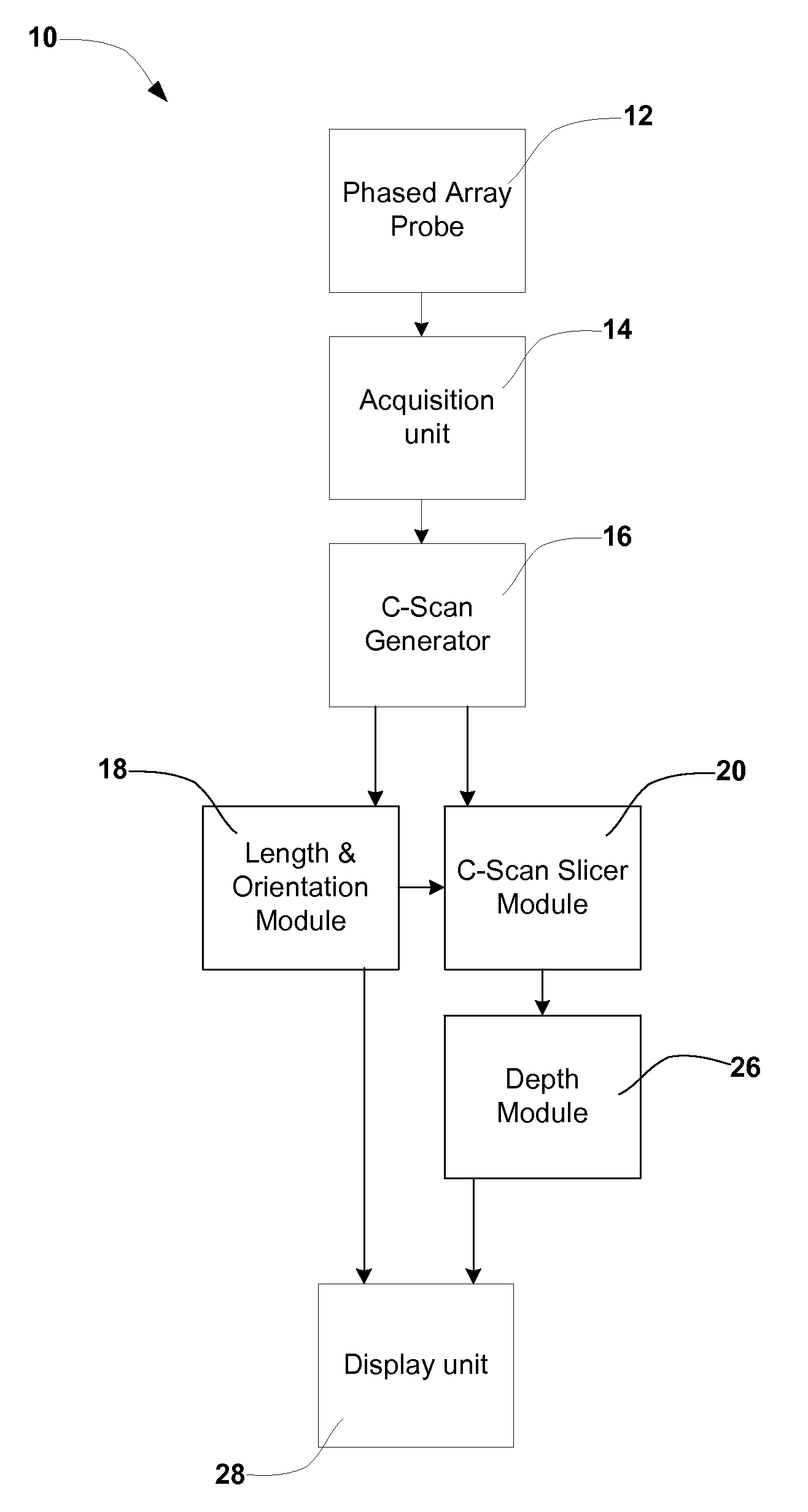
Figure 1 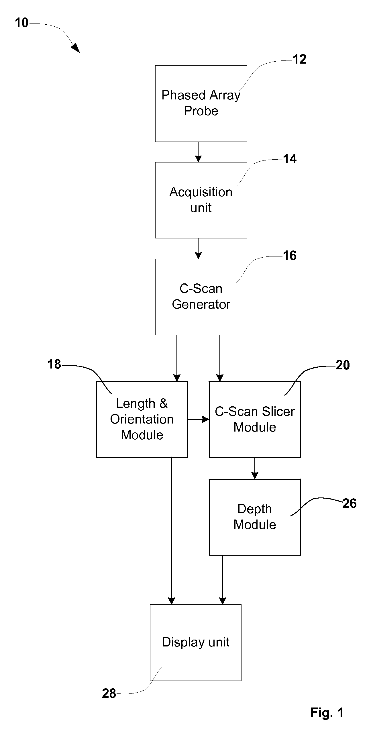
Figure 2 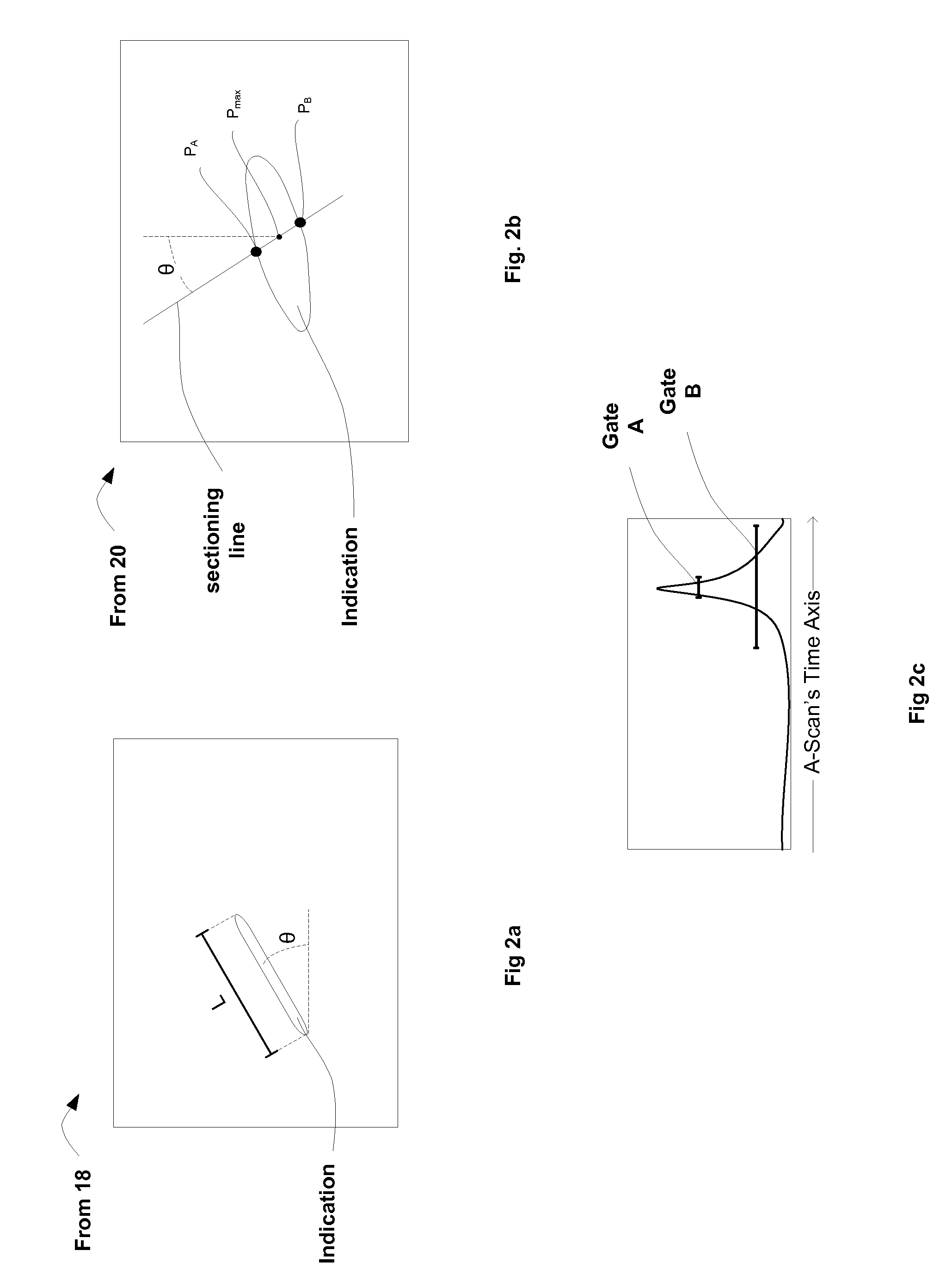
Figure 3
Abstract
Description
FIELD OF THE INVENTION
[0001] The present disclosure generally relates to a method and a system for inspecting and identifying flaws in test objects using phased array ultrasonic systems and, more particularly, to an improved method of sizing defects in the test objects and to an apparatus with the devised improvement in the phased systems, accordingly.BACKGROUND OF THE INVENTION
[0002] Ultrasonic phased array (later as “PA”) instruments provide a significant advantage for many applications because they display a cross section of the region being inspected, thereby facilitating the visualization of an imperfection, its feature, location and size, typically sought by ultrasonic inspection. Another significant advantage of ultrasonic phased array instruments is that they provide much higher inspection speed and therefore higher productivity in comparison to single element probe systems.
[0003] For inspecting a pipe during production, typically a PA system includes a linear phased array prob...
Examples
Embodiment Construction
[0018]Referring to FIG. 1, a phased array ultrasonic system 10 embodies, besides other conventional components, a PA probe 12 and an acquisition unit 14 and a C-scan generator 16 which is used to produce C-Scans according to the echo signal acquired by acquisition unit 14. C-scan generator 16 provides two C-scans, namely Gate A C-scan and Gate B C-scan. The two C-scans are then provided to two signal analyzer modules, the length & orientation module 18 and the C-scan slicer module 20, respectively. Gate A C-Scan is used to obtain indication orientation θ and length L in length & orientation module 18. Gate B C-Scan is used to obtain a C-scan slice from the orientation θ in C-scan slicer module 20. The slice is then used by the depth module 26 to find the size in depth D of the Indication. Three measurements, namely the length L, orientation θ and depth D, are then displayed by a display unit 28.
[0019]It should be noted that, PA inspection on a pipe is herein used in this embodiment ...