
Heat exchanger
a technology of heat exchanger and heat exchanger body, which is applied in the field of heat exchanger, can solve the problems of fluid leakage into the surrounding atmosphere, and achieve the effect of increasing the amount of tim
Patent Information
- Authority / Receiving Office
- US · United States
- Current Assignee / Owner
- Publication Date
- 2016-05-12
Smart Images
Figure 1 
Figure 2 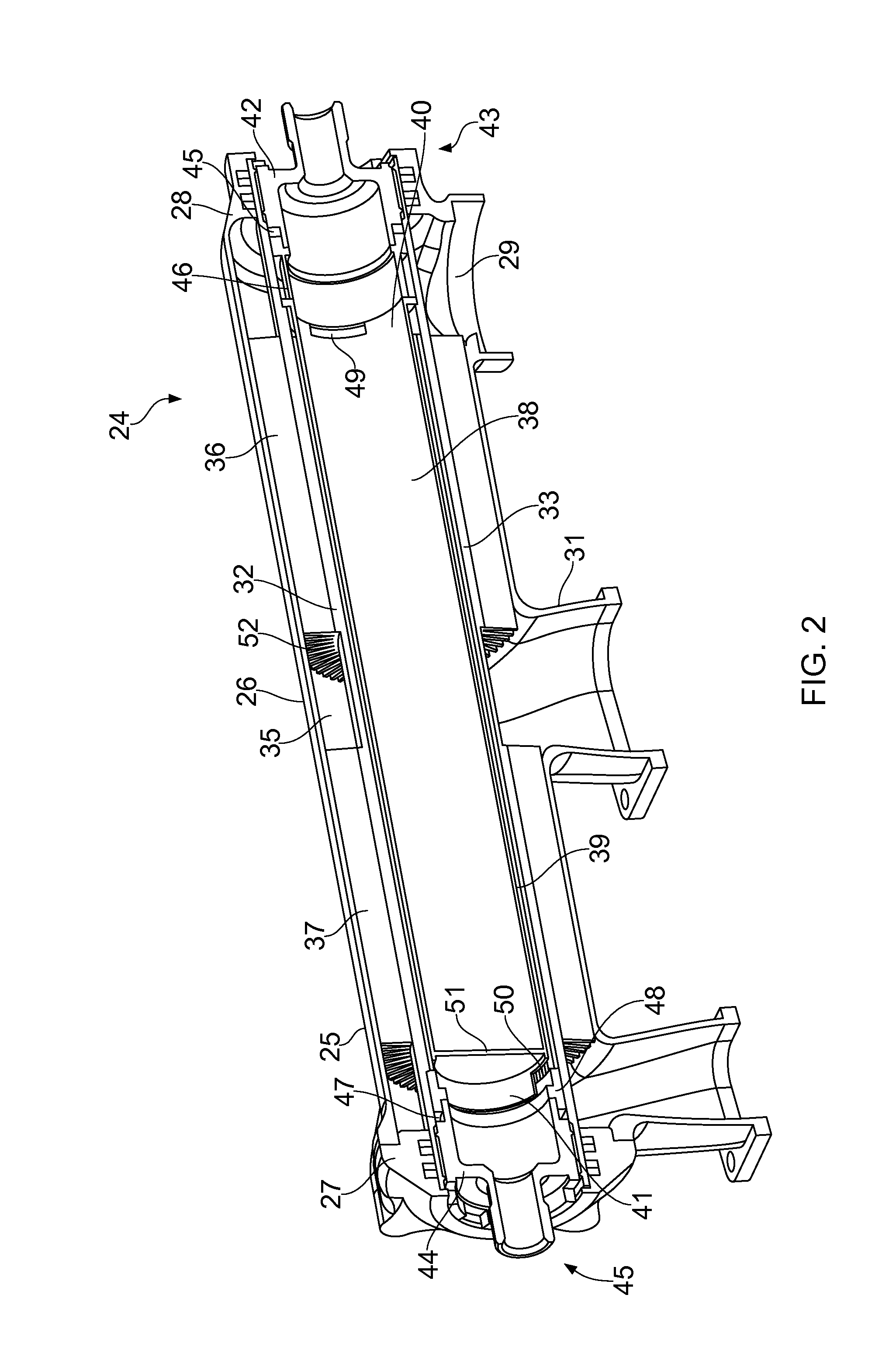
Figure 3
Abstract
Description
FIELD OF THE INVENTION
[0001] The present invention relates to a heat exchanger, particularly, but not exclusively to a heat exchanger for a gas turbine engine.BACKGROUND OF THE INVENTION
[0002] It is known to use a heat exchanger in a gas turbine engine for heating fuel prior to combustion using heat contained within the high pressure air leaving the combustor or using heat contained within engine's oil system. The pressurised air / oil cooled within the heat exchanger is used to cool turbine components.
[0003] Various types of heat exchangers are known including tubular heat exchangers and plate / fin heat exchangers.
[0004] Tubular heat exchangers comprise a tubular shell through which a first fluid flows. The tubular shell may contain baffles for directing the flow of the first fluid along a convoluted path from an inlet to an outlet. A number of tubes (a tube bundle) carrying a second fluid extend from a tube manifold or tube sheet within the tubular shell so that heat exchange can occur b...
Examples
first embodiment
[0090]In the first embodiment, the second annular passage 39 is divided by axially extending, circumferentially spaced radial inner fins 53. The inner fins 53 are integral with the inner surface 34 of the tubular element 32 and are formed by machining the inner surface 34 of the tubular element 32 by electro-discharge wire cutting.
[0091]The inner fins 53 divide the second annular passage 39 / second fluid flow path into a series of axially aligned channels extending from the first axial end 40 of the inner sleeve 38 to the second axial end 41 of the inner sleeve 38.
[0092]The axially extending, circumferentially spaced radial inner fins 53 are adapted to divide the second annular passage into a plurality of convoluted channels. Each convoluted channel has an inlet 54 at the first axial end 40 of the inner sleeve 32, a series of axially aligned portions 55 with adjacent axially aligned portions being interconnected proximal the axial ends 40, 41 of the inner sleeve 32 and an outlet 56 a...
second embodiment
[0097]the present invention is shown in FIGS. 4 and 5. Many features are common between the two embodiments shown and the same reference numerals are used where appropriate.
[0098]In this embodiment, the inner surface 34 of the tubular element 32 comprises integral spirally / helically extending, circumferentially spaced radial inner fins 57 which formed into the inner surface 34 using thread milling. These inner fins 57 divide the second annular passage 39 into a series of aligned spiral / helical channels extending from the first axial end 40 of the inner sleeve 38 to the second axial end 41 of the inner sleeve 38.
[0099]The second axial end 41 of the inner sleeve 38 comprises a series of circular apertures 58 which provide fluid communication between the second annular passage 39 and the outlet adapter 44 (via the bore of the inner sleeve 38). At the first axial end 40 of the inner sleeve 38, a cut-out 49 is provided to allow fuel to enter the second annular passage.
[0100]Fuel entering...