
Anti-locking mechanism of spherical compressor rotor, Anti-locking power mechanism of spherical compressor, and spherical compressor
Patent Information
- Authority / Receiving Office
- US · United States
- Current Assignee / Owner
- Publication Date
- 2016-11-17
Smart Images
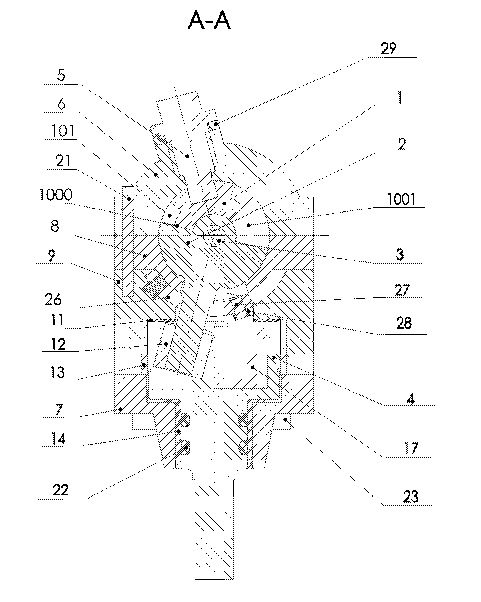
Figure 1 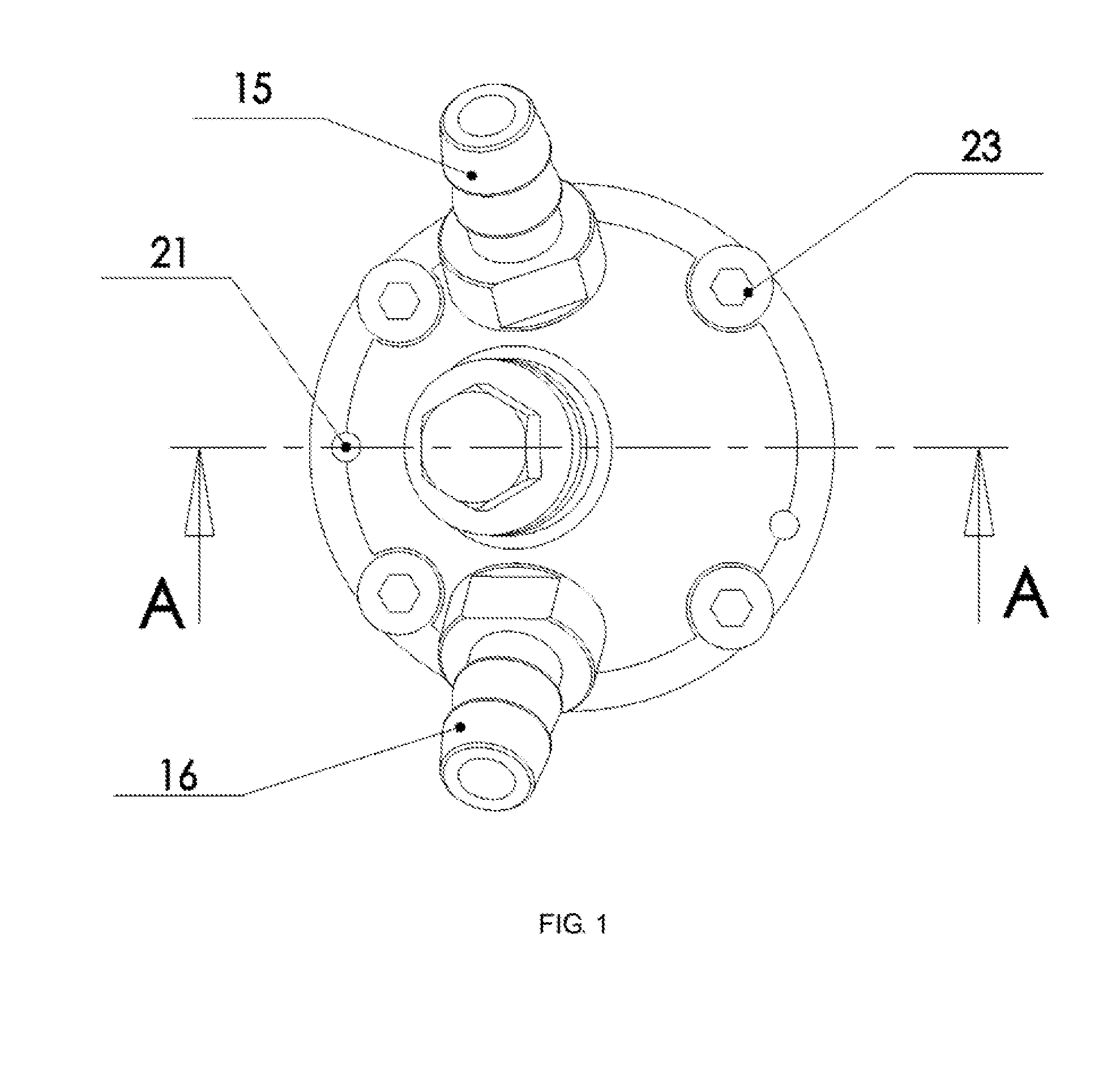
Figure 2 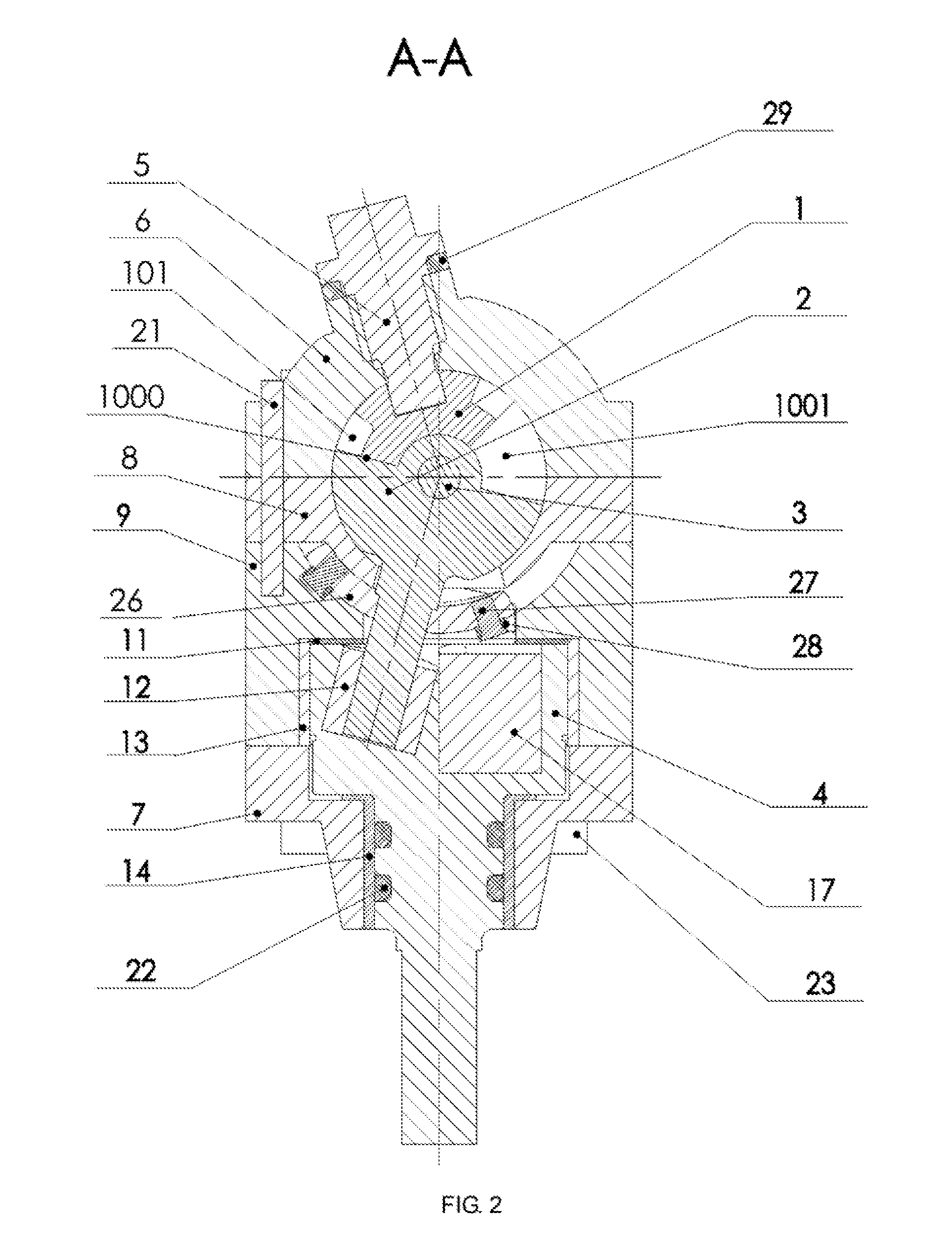
Figure 3
Abstract
Description
CROSS-REFERENCE TO RELATED APPLICATIONS
[0001] This application is a continuation of International Patent Application No. PCT / CN2015 / 073501 with a filing date of Mar. 2, 2015, designating the United States, now pending, and further claims priority to Chinese Patent Application No. 201410100390.X with a filing date of Mar. 18, 2014, No. 201410554836.6 with a filing date of Oct. 19, 2014. The content of the aforementioned applications, including any intervening amendments thereto, are incorporated herein by reference.TECHNICAL FIELD
[0002] The present invention relates to a spherical compressor, and particularly relates to an anti-locking mechanism of a spherical compressor rotor, an anti-locking power mechanism of a spherical compressor, and a spherical compressor.BACKGROUND OF THE PRESENT INVENTION
[0003] The spherical compressor technology is a new subject developed in recent years. The structure and the principle of the spherical compressor are completely different from those of the exi...
Examples
Embodiment Construction
[0073]The details of the present invention can be understood more clearly in combination with the drawings and the description of the specific embodiments of the present invention. However, the specific embodiments of the present invention described herein are merely used for the purpose of explaining the present invention, rather than understood to limit the present invention by any means. Enlightened by the present invention, those skilled in the art can concept any possible deformations based on the present invention, all of which should be regarded as belonging to the scope of the present invention.
[0074]As shown in FIG. 1 and FIG. 2 or FIG. 16 and FIG. 17, the spherical compressor provided in some embodiments of the present invention comprises: a cylinder head 6, a piston 1, a cylinder 8, a turntable 2, an anti-locking device, a main shaft support 7 and a main shaft 4, wherein as shown in FIG. 5 and FIG. 6 or FIG. 20 and FIG. 21, the cylinder head 6 is a hollow semi-spherical s...