
Ladar Receiver Range Measurement using Distinct Optical Path for Reference Light
a reference light and laser receiver technology, applied in the direction of instruments, measurement devices, using reradiation, etc., can solve the problems of large data bandwidth use, large size, large weight, and large power requirements of conventional ladar solutions for computer vision problems, and limit their effective use to costly applications
Patent Information
- Authority / Receiving Office
- US · United States
- Current Assignee / Owner
- Publication Date
- 2017-08-24
Smart Images
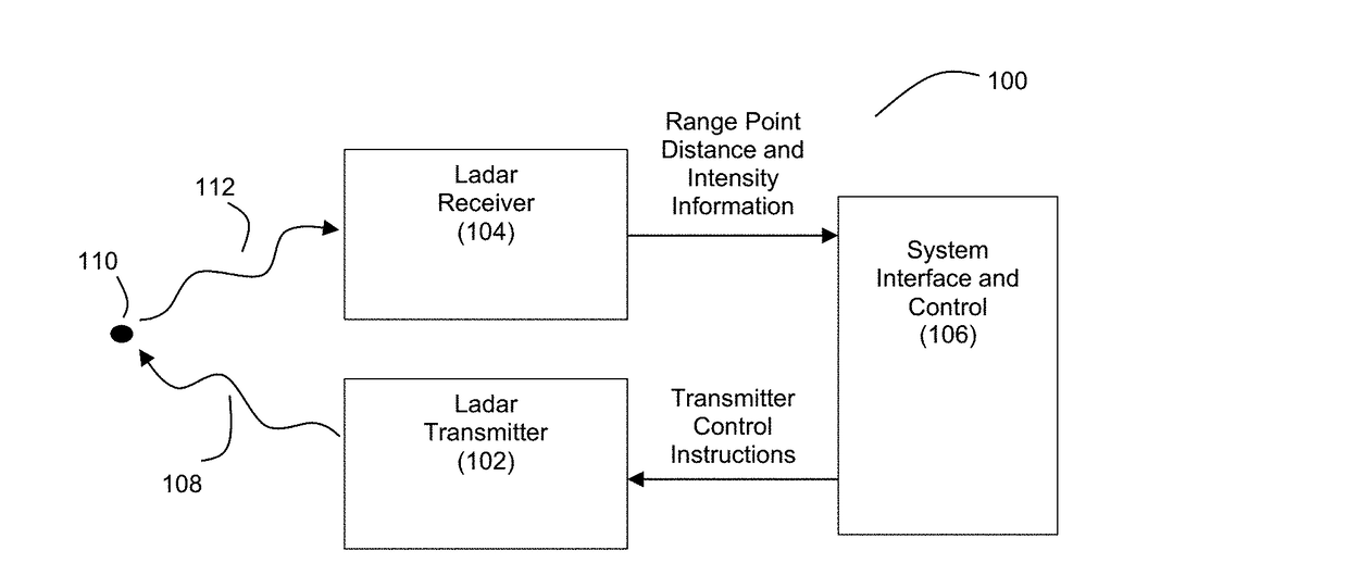
Figure 1 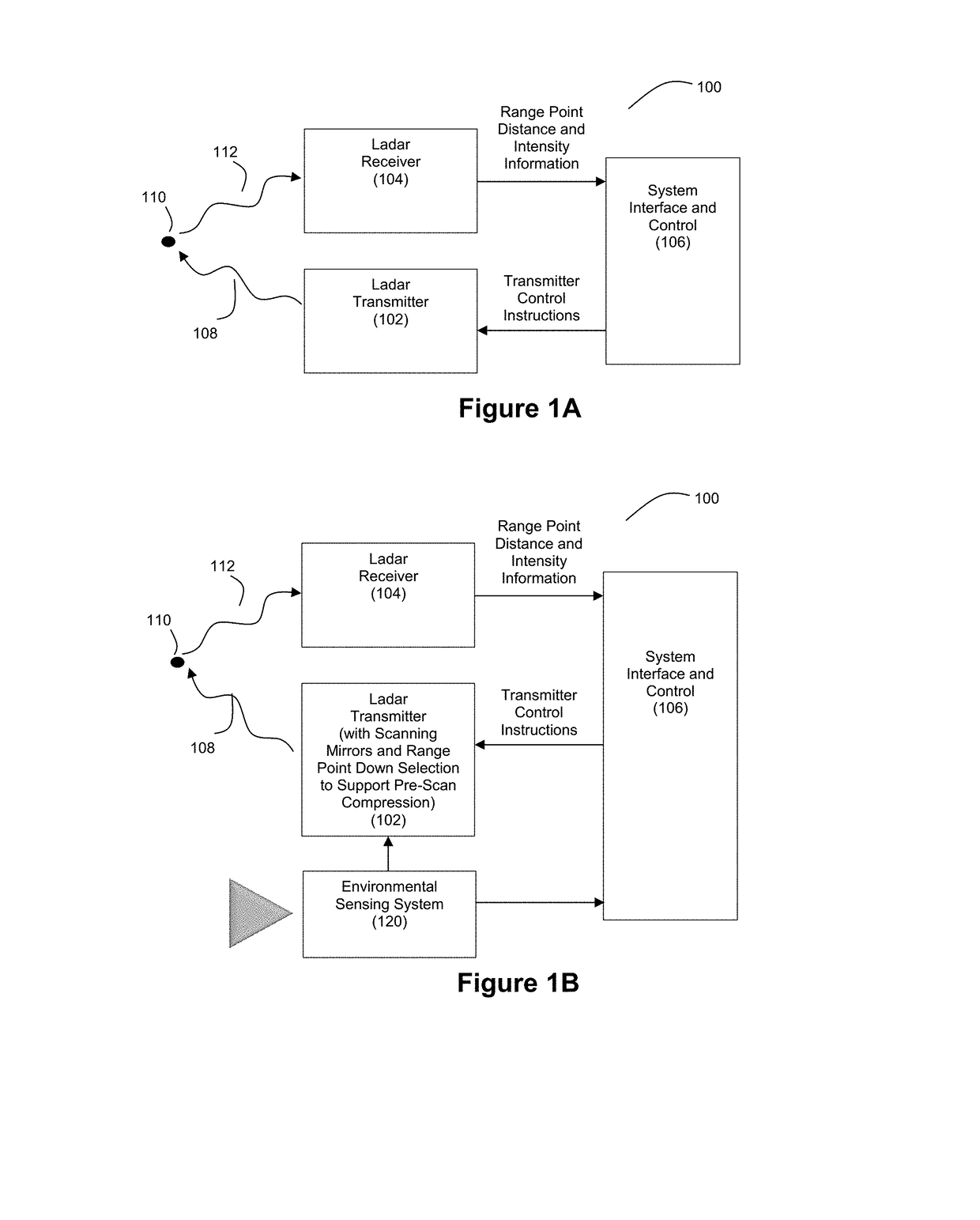
Figure 2 
Figure 3
Abstract
Description
CROSS-REFERENCE AND PRIORITY CLAIM TO RELATED PATENT APPLICATION
[0001] This patent application claims priority to U.S. provisional patent application 62 / 297,112, filed Feb. 18, 2016, and entitled “Ladar Receiver”, the entire disclosure of which is incorporated herein by reference.
[0002] This patent application is also related to (1) U.S. patent application Ser. No. ______, filed this same day and entitled “Adaptive Ladar Receiving Method” (said application being identified by Thompson Coburn attorney docket number 56976-163576), (2) U.S. patent application Ser. No ______, filed this same day and entitled “Adaptive Ladar Receiver” (said application being identified by Thompson Coburn attorney docket number 56976-164105), (3) U.S. patent application Ser. No. ______, filed this same day and entitled “Ladar Receiver with Advanced Optics” (said application being identified by Thompson Coburn attorney docket number 56976-164106), and (4) U.S. patent application Ser. No. ______, filed this s...
Examples
Embodiment Construction
[0031]FIG. 1A illustrates an example embodiment of a ladar transmitter / receiver system 100. The system 100 includes a ladar transmitter 102 and a ladar receiver 104, each in communication with system interface and control 106. The ladar transmitter 102 is configured to transmit a plurality of ladar pulses 108 toward a plurality of range points 110 (for ease of illustration, a single such range point 108 is shown in FIG. 1A). Ladar receiver 104 receives a reflection 112 of this ladar pulse from the range point 110. Ladar receiver 104 is configured to receive and process the reflected ladar pulse 112 to support a determination of range point distance and intensity information. Example embodiments for innovative ladar receivers 104 are described below.
[0032]In an example embodiment, the ladar transmitter 102 can take the form of a ladar transmitter that includes scanning mirrors and uses a range point down selection algorithm to support pre-scan compression (which can be referred herei...