
Method and Apparatus for Firetube Boiler and Ultra Low NOx Burner
a technology of nox burner and firetube boiler, which is applied in the direction of furnace-tube steam boiler, steam boiler components, flue gas purification components, etc., can solve the problems of hampered innovation in low-emission burners, inability to substantially self-control forced fgr, and complicated control, etc., to achieve low nox emissions, high thermal efficiency, and low electricity consumption
Patent Information
- Authority / Receiving Office
- US · United States
- Patent Type
- Applications(United States)
- Current Assignee / Owner
- Publication Date
- 2018-05-10
Smart Images
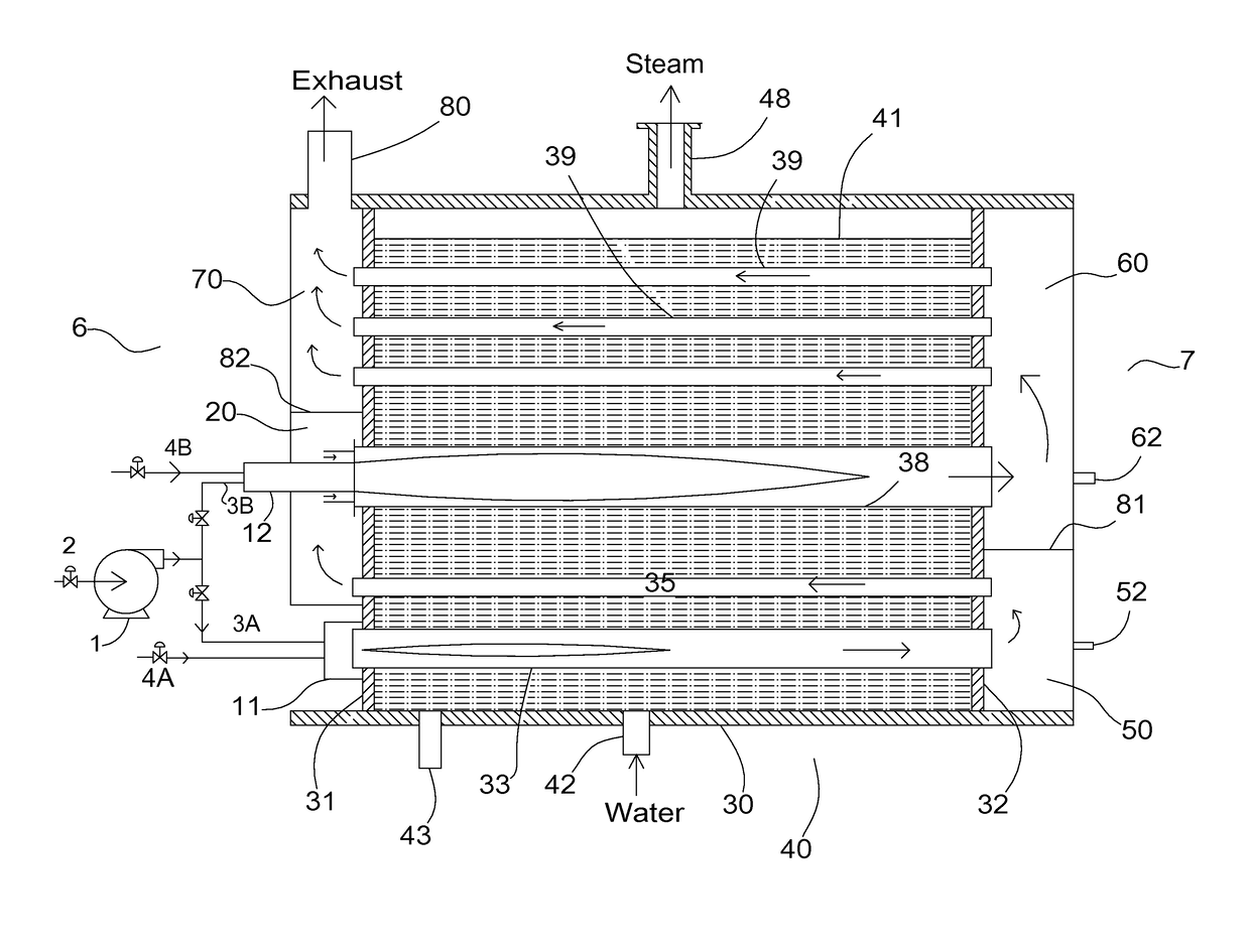
Figure 1 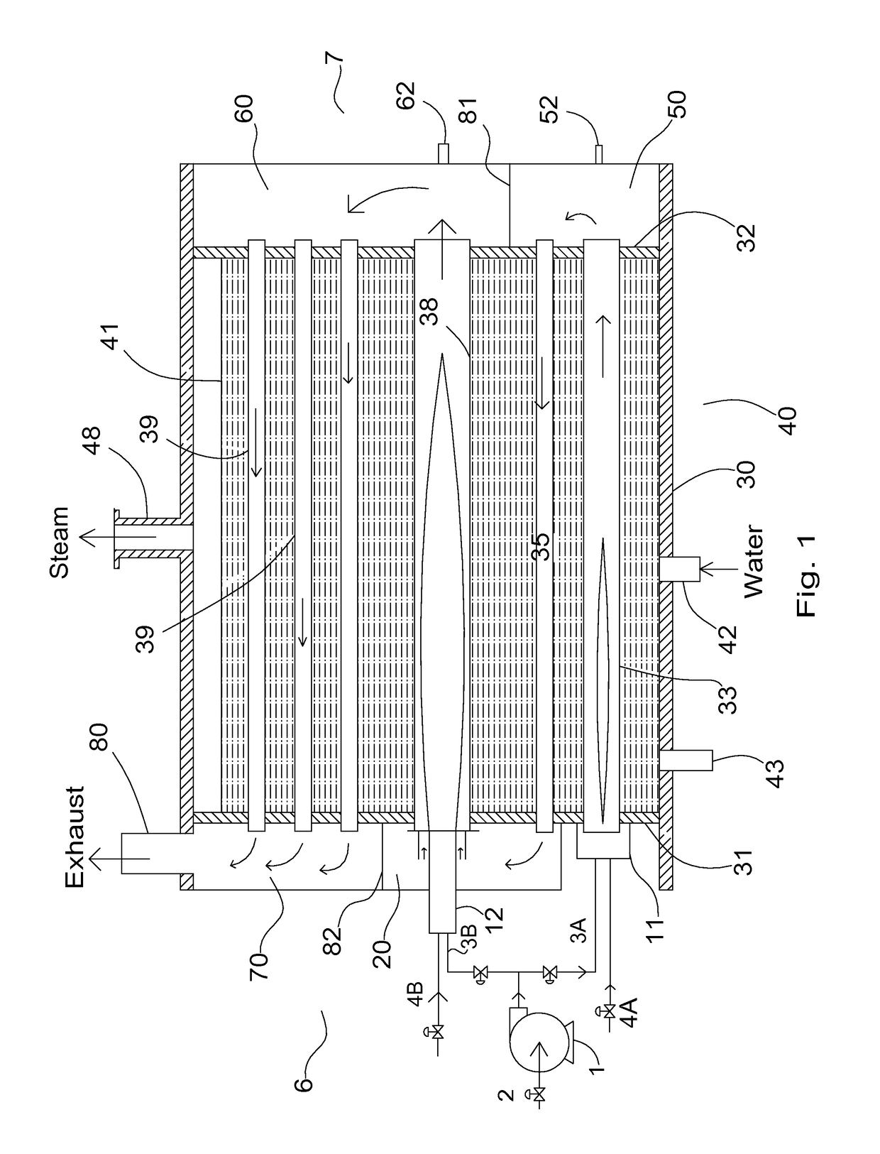
Figure 2 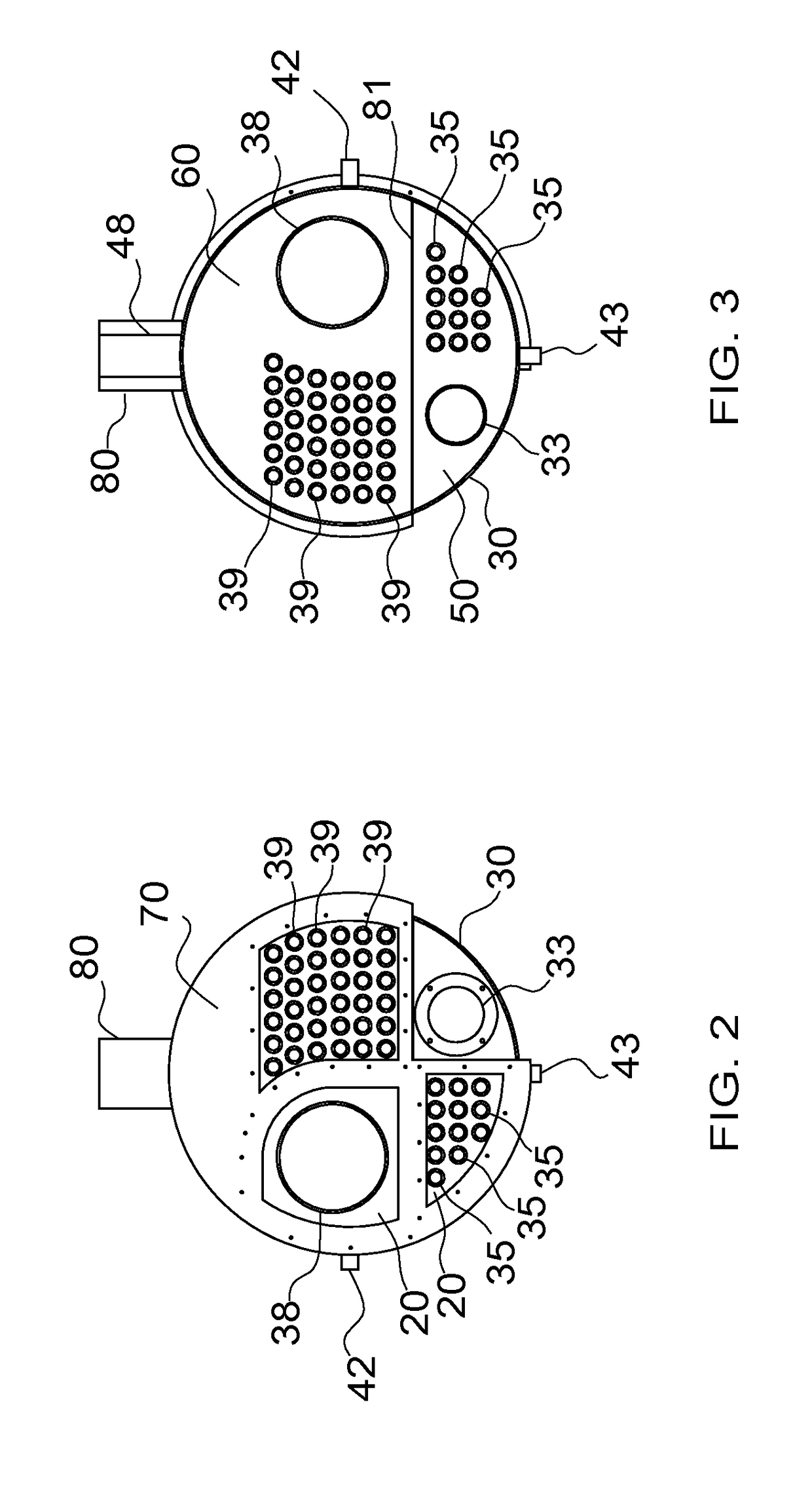
Figure 3
Abstract
Description
[0001] This is a continuation of application Ser. No. 14 / 941,842 filed on Nov. 16, 2015.BACKGROUND OF THE INVENTION1. Field of the Invention
[0002] This invention relates generally to a firetube boiler and a burner system for the production of hot water or steam. More particularly, this invention relates to the production of hot water or steam using a firetube boiler and a burner system that are designed to produce ultra low NOx emissions and higher efficiency at the same time. The firetube boiler and the burner of this invention are specifically designed to work with each other.2. Description of the Related Art
[0003] Boilers are widely used for the generation of hot water and steam. A conventional boiler (excluding Heat Recovery Steam Generator or HRSG) comprises a furnace in which fuel is burned, and surfaces typically in the form of steel tubes to transfer heat from the flue gas to the water. A conventional boiler has a furnace that burns a fossil fuel or, in some installations, wast...
Examples
Embodiment Construction
[0026]For the purpose of this invention, a burner shall mean a device to produce one or more flames in the firetube boiler of the current invention in a controlled manner, taking inputs from at least one fuel source and an oxidizer source such as air. The two stages of the burner disclosed in this invention could arguably be referred to as two separate burners by anyone skilled in the art. Such change of nomenclature does not create a new invention outside the scope of the current invention.
[0027]FIG. 1 shows a schematic view of an apparatus for the current invention. A boiler 5 has a cylindrical shell 30, which is welded to a front tube sheet 31 and a rear tube sheet 32 to form a pressure vessel 40. Furnace tubes 33 and 38 are positioned in the shell 30 to extend the length of the shell from tube sheet 31 and to tube sheet 32, and sealingly attached (typically welded) to these tube sheets per firetube boiler codes. A plurality of firetubes 35 and 39 are also positioned in the shell...