
Hybrid vehicle and control method therefor
a hybrid vehicle and control method technology, applied in the field of hybrid vehicles, can solve the problems of drag torque (mechanical loss), drag torque (mechanical loss), and drag torque (mechanical loss) generated in the first motor, and achieve the effect of reducing the torque (driving torque) of the driving shaft, reducing the drag torque, and reducing the regeneration torque and drag torque in the first motor
Patent Information
- Authority / Receiving Office
- US · United States
- Patent Type
- Applications(United States)
- Current Assignee / Owner
- Publication Date
- 2018-09-20
- Estimated Expiration
- Not applicable · inactive patent
Smart Images
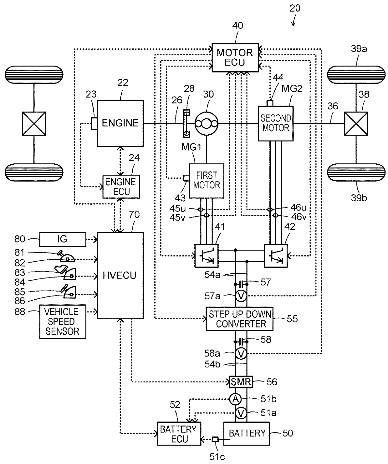
Figure 1 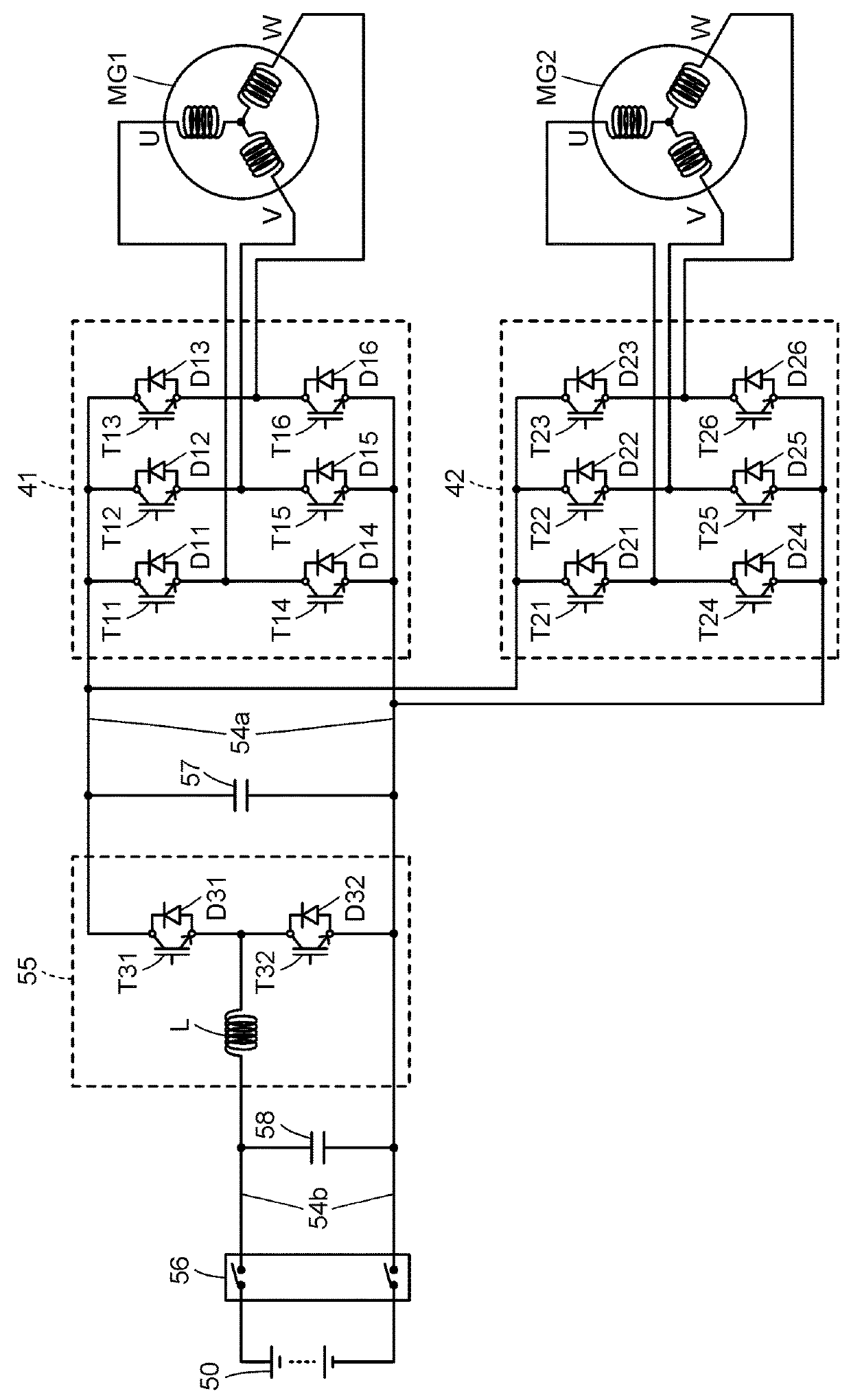
Figure 2 
Figure 3
Abstract
Description
CROSS-REFERENCE TO RELATED APPLICATIONS
[0001] The disclosure of Japanese Patent Application No. 2017-052606 filed on Mar. 17, 2017 including the specification, drawings and abstract is incorporated herein by reference in its entirety.BACKGROUND1. Technical Field
[0002] The present disclosure relates to a hybrid vehicle and a control method therefor.2. Description of Related Art
[0003] As a hybrid vehicle of this type, there has been proposed a vehicle including an engine, a first motor, and a planetary gear mechanism including a carrier, a sun gear, and a ring gear that are connected to the engine, the first motor, and an output member coupled with driving wheels. The hybrid vehicle also includes a second motor connected to the output member, an inverter that drives the first motor and the second motor, and a battery connected to the inverter through an electric power line (see, for example, Japanese Patent Application Publication No. 2013-203116). When an accelerator is on while the hyb...
Examples
Embodiment Construction
[0021]Now, modes for carrying out the present disclosure will be described in detail based on embodiments.
[0022]FIG. 1 is a block diagram illustrating an outlined configuration of a hybrid vehicle 20 as one embodiment of the present disclosure. FIG. 2 is a block diagram illustrating an outlined configuration of an electric drive system including a first motor MG1 and a second motor MG2. As illustrated in the drawings, the hybrid vehicle 20 of the embodiment includes an engine 22, a planetary gear set 30, a first motor MG1, a second motor MG2, a first inverter 41, a second inverter 42, a step up-down converter 55, a battery 50 as an electric storage device, a system main relay (also abbreviated to “SMR”) 56, and a hybrid electronic control unit (referred to as “HVECU” below) 70.
[0023]The engine 22 is configured as an internal combustion engine that outputs motive power by using fuel such as gasoline, and gas oil. The operation of the engine 22 is controlled by an engine electronic co...