
Motor pump
a technology of motor pump and potting material, which is applied in the direction of liquid fuel engines, machines/engines, mechanical equipment, etc., can solve the problems of motor casing deformation due to thermal expansion, motor casing deformation due to heat generation, and electric leakage, so as to improve the flow of potting material, prevent deformation of motor casing, and improve the effect of potting material
Patent Information
- Authority / Receiving Office
- US · United States
- Current Assignee / Owner
- Publication Date
- 2019-08-22
Smart Images
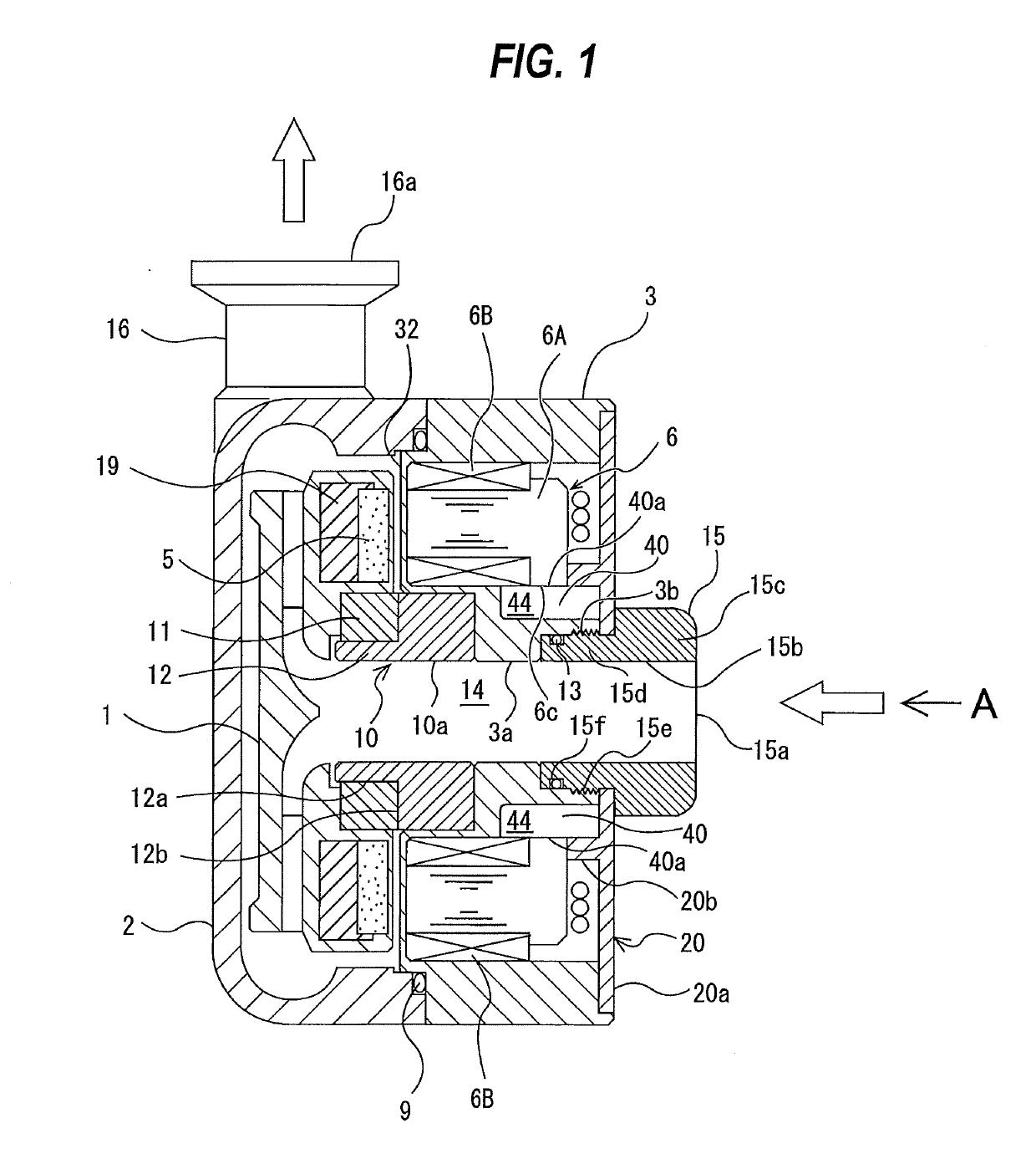
Figure 1 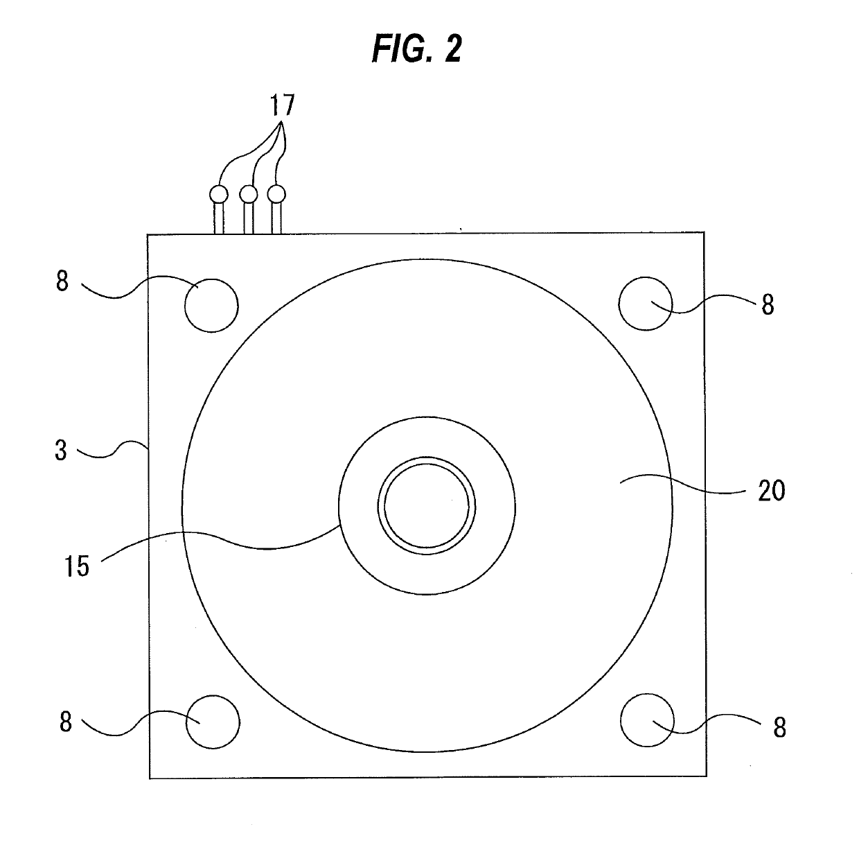
Figure 2 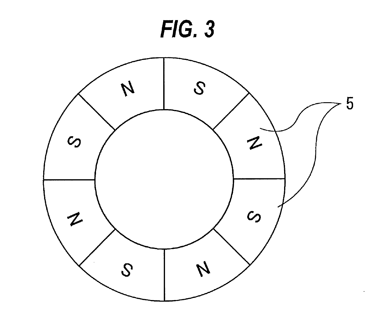
Figure 3
Abstract
Description
CROSS REFERENCE TO RELATED APPLICATION
[0001] This document claims priority to Japanese Patent Application Number 2018-027698 filed Feb. 20, 2018, the entire contents of which are hereby incorporated by reference.BACKGROUND
[0002] Japanese laid-open patent document No. 2544825 discloses a conventional example of a motor pump that rotates an impeller having permanent magnets embedded therein by a magnetic field generated by a motor stator. The motor pump described in this patent document 1 includes the impeller in which permanent magnets are embedded and the motor stator disposed so as to face the impeller. The impeller is rotatably supported by one spherical bearing. This spherical bearing is a so-called dynamic pressure bearing, and is configured to be able to tiltably support the impeller while rotatably supporting the impeller.
[0003] The motor stator has a plurality of stator coils. When three-phase currents are passed through these stator coils, a rotating magnetic field is generated...
Examples
Embodiment Construction
[0040]Hereinafter, embodiments will be described in detail with reference to the drawings.
[0041]FIG. 1 is a cross-sectional view showing a motor pump according to an embodiment, and FIG. 2 is a view showing the motor pump shown in FIG. 1 as viewed in a direction of arrow A. This motor pump includes an impeller 1 in which a plurality of permanent magnets 5 are embedded, a motor stator 6 for generating a magnetic force acting on these permanent magnets 5, a pump casing 2 in which the impeller 1 is disposed, a motor casing 3 in which the motor stator 6 is disposed, and a bearing 10 supporting a radial load and a thrust load of the impeller 1. The motor stator 6 and the bearing 10 are disposed at a suction side of the impeller 1.
[0042]The pump casing 2 and the motor casing 3 are fixed to each other by a plurality of coupling bolts 8 shown in FIG. 2. An O-ring 9 as a sealing member is provided between the pump casing 2 and the motor casing 3. The impeller 1 and the motor casing 3 are opp...