
Sputtering apparatus
a technology of sputtering apparatus and sputtering tube, which is applied in the direction of vacuum evaporation coating, plasma technique, coating, etc., can solve the problems of large potential difference between two ends of the antenna, increase in the impedance of the antenna, uneven thickness of the film that is generated, etc., to improve the uniformity of the film formation, improve the uniformity of the plasma, and generate efficient
Patent Information
- Authority / Receiving Office
- US · United States
- Patent Type
- Applications(United States)
- Current Assignee / Owner
- Publication Date
- 2021-05-20
Smart Images
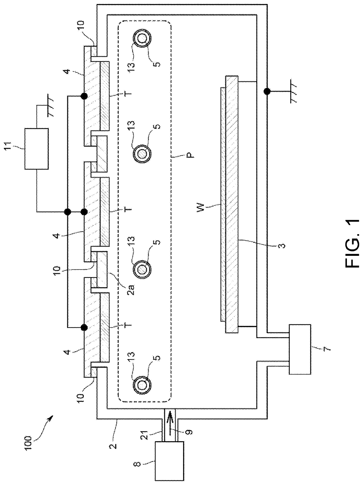
Figure 1 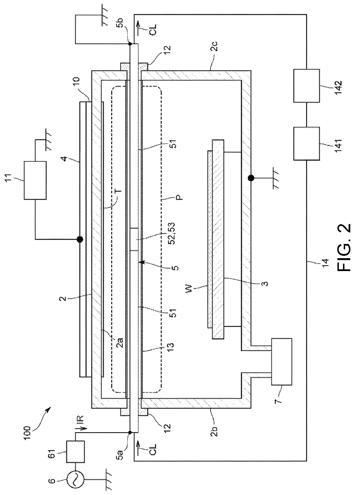
Figure 2 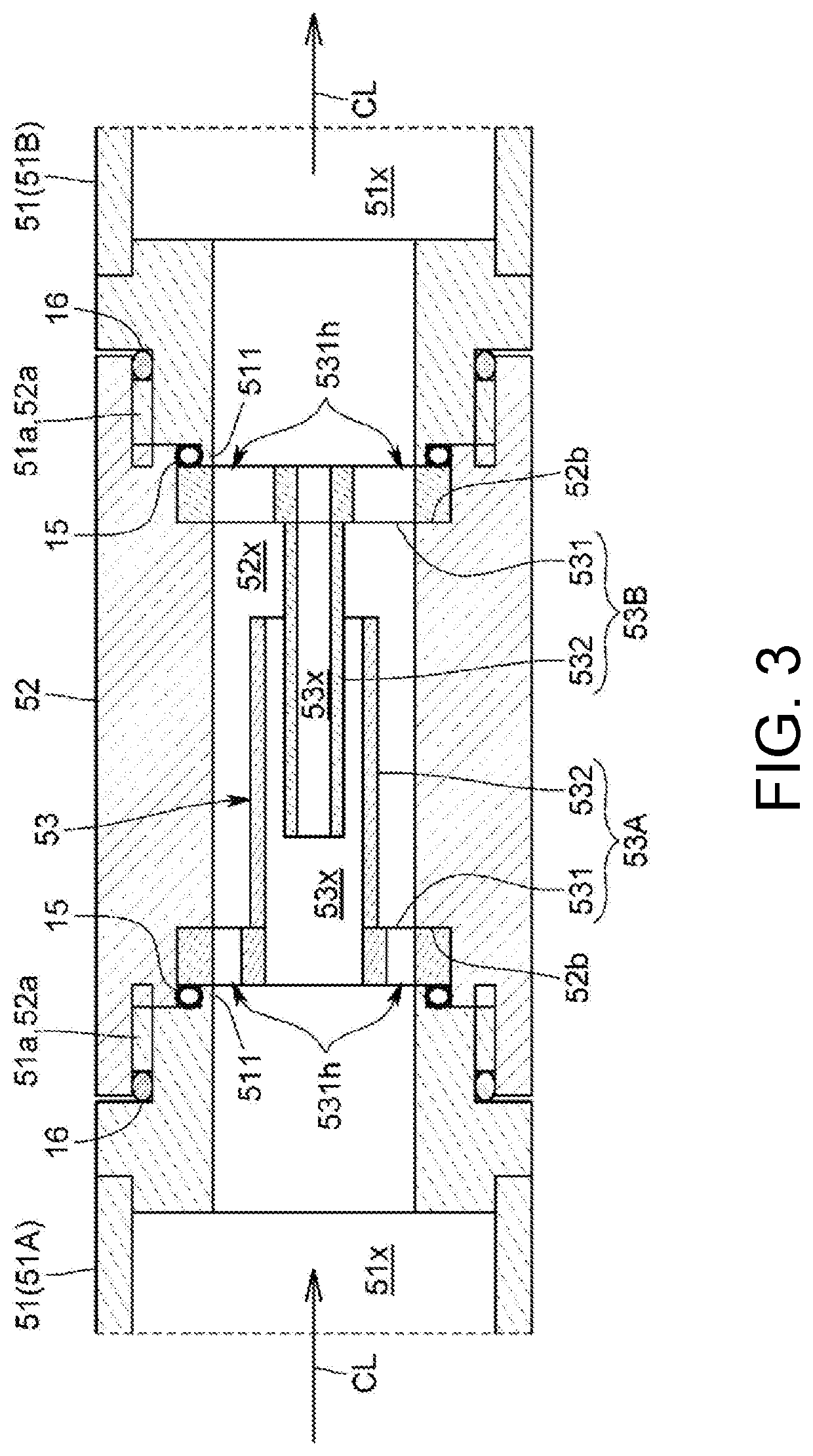
Figure 3
Abstract
Description
BACKGROUND OF THE INVENTIONTechnical Field
[0001] The present invention relates to a sputtering apparatus that performs sputtering on a target with plasma to form a film on a substrate.Related Art
[0002] As this type of sputtering apparatus, a magnetron sputtering apparatus is known. The magnetron sputtering apparatus is configured to form a magnetic field at a front surface of a target by a magnet arranged at a back surface of the target so as to generate plasma and to cause ions in the plasma to collide with the target, and thereby cause sputtered particles to fly out from the target.
[0003] In the conventional magnetron sputtering apparatus, sparseness and density plasma is generated in the vicinity of the front surface of the target. Accordingly, the target is not uniformly consumed, and a utilization rate of the target is lowered. In addition, since the target is not uniformly consumed, a film that is generated also has an uneven thickness.
[0004] On the other hand, as disclosed in pat...
Examples
other modification embodiments
[0108]Moreover, the present invention is not limited to the above-described embodiment.
[0109]For example, in the embodiment, the antenna has a straight line shape; however, the antenna may have a curved or bent shape. In this case, the metal pipe may have a curved or bent shape, and the insulating pipe may have a curved or bent shape.
[0110]The extension portions of the electrode of the embodiment have a cylindrical shape; however, the extension portion may have a rectangular cylinder shape other than the cylindrical shape or may have a flat plate shape or a curved or bent plate shape.
[0111]In the embodiment, the capacitor 53 has a two-cylinder structure consisting of two extension portions having the cylindrical shape; however, as illustrated in FIG. 8, three cylindrical extension portions 532 or more may be coaxially disposed. In this case, the extension portion 532 of the first electrode 53A and the extension portion 532 of the second electrode 53B are configured to be alternately...