
Chopper system and method
a chopper and frequency technology, applied in the field of systems, can solve the problems of additional implementation outlay, undesirable stabilization or overshooting behavior, and additional delay times,
Patent Information
- Authority / Receiving Office
- US · United States
- Patent Type
- Applications(United States)
- Current Assignee / Owner
- Publication Date
- 2021-11-04
Smart Images
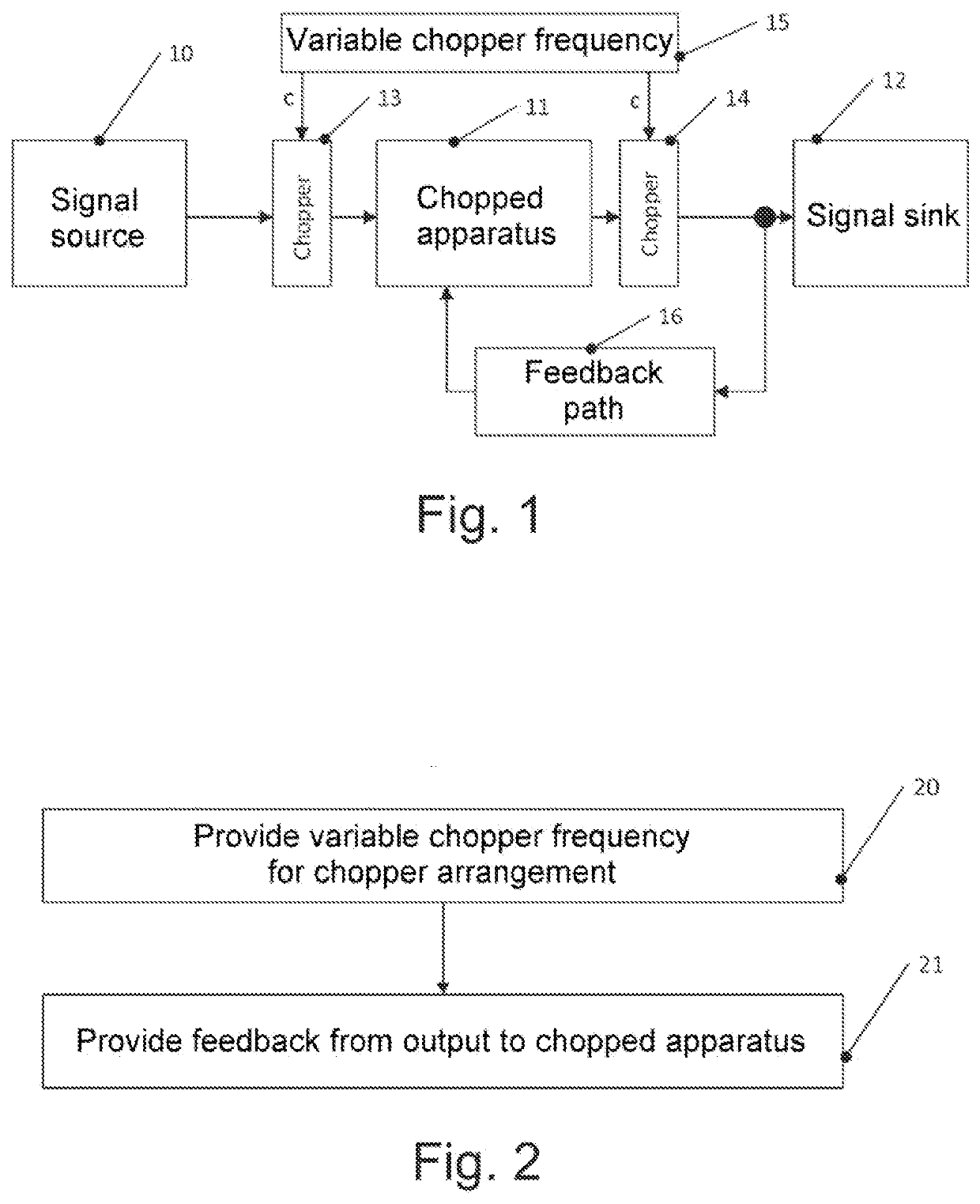
Figure 1 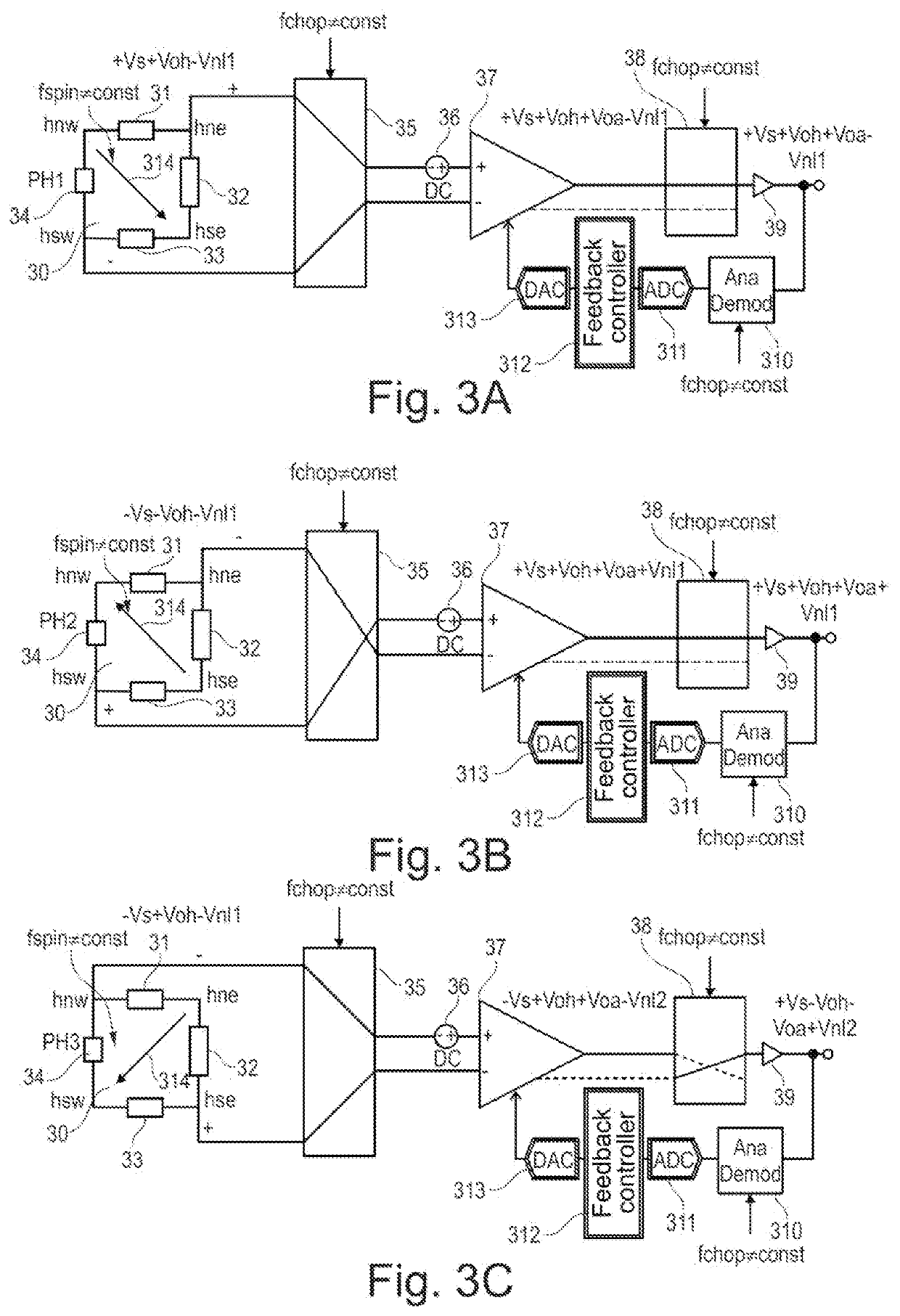
Figure 2 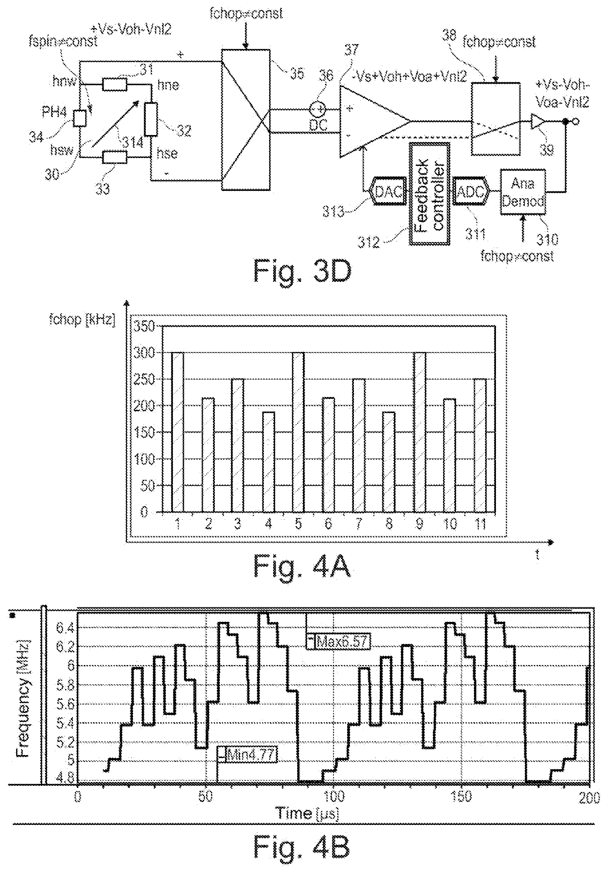
Figure 3
Abstract
Description
CROSS REFERENCE TO RELATED APPLICATION
[0001] This application claims priority to German Patent Application No. 102020111914.3, filed on May 4, 2020, the contents of which are incorporated by reference herein in their entirety.TECHNICAL FIELD
[0002] The present application concerns systems that employ chopping, and corresponding methods.BACKGROUND
[0003] Chopping is a technique that involves an input signal and an output signal of an apparatus each being modulated with a chopper signal that has a chopper frequency. The apparatus can be an analog-to-digital converter or an amplifier, for example, and is referred to generally as a chopped apparatus in this application. By way of example, such a chopper signal can alternately assume values of +1 and −1 at a chopper frequency, and the input signal and the output signal of the chopped apparatus are multiplied by this signal for the purpose of modulation.
[0004] This chopping eliminates a DC voltage offset of the chopped apparatus or at least dec...
Examples
example 5
[0075] System according to one of examples 1 to 4, wherein the feedback path has a filter frequency that is lower than a minimum chopper frequency of the variable chopper frequency by at least a factor of 2.
[0076]Example 6. System according to one of examples 1 to 5, wherein the feedback path comprises a demodulator, which is configured to operate based on the chopper signal, and an integrator.
[0077]Example 7. System according to one of examples 1 to 6, moreover comprising a spinning current Hall sensor, wherein an output of the spinning current Hall sensor is coupled to an input of the chopper modulator, wherein the spinning current Hall sensor is configured to be operated at a variable spinning frequency that is an integer multiple of the variable chopper frequency.
[0078]Example 8. Method, comprising:
[0079]providing a chopper signal having a variable chopper frequency to a chopper arrangement, and
[0080]providing feedback from an output of the chopper arrangement to a chopped appar...
example 13
[0086] Method according to one of examples 8 to 12, wherein the providing of the feedback comprises demodulating an output signal of the chopper arrangement based on the chopper signal, and integrating the demodulated output signal.
[0087]Example 14. Method according to one of examples 8 to 13, moreover comprising operating a Hall sensor using a spinning current technique, wherein an output of the Hall sensor is coupled to an input of the chopper arrangement, wherein the spinning current technique is operated at a variable spinning frequency that is an integer multiple of the variable chopper frequency.