
Rotor assembling method, and control device for rotor assembly apparatus
a control device and rotor assembly technology, applied in the direction of dynamo-electric machines, magnetic circuit rotating parts, magnetic circuit shape/form/construction, etc., can solve the problems of reducing the performance of the rotating electric machine in which the rotor is provided, and the permanent magnet cannot be inserted into the hole portion, so as to suppress the reduction of the insertability of the permanent magnet and improve the performance of the rotating electric machine. , the effect of suppressing the deformation of the permanen
Patent Information
- Authority / Receiving Office
- US · United States
- Patent Type
- Applications(United States)
- Current Assignee / Owner
- Publication Date
- 2022-01-27
Smart Images
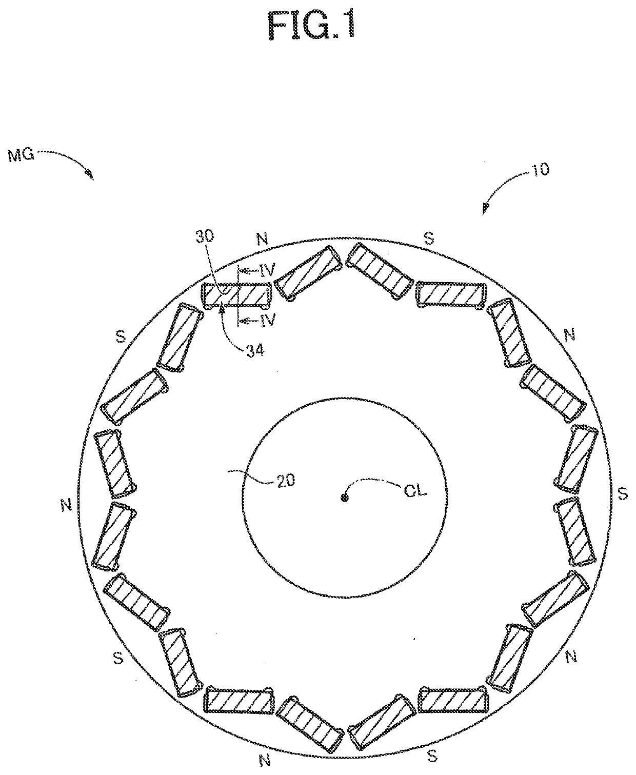
Figure 1 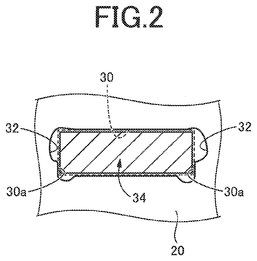
Figure 2 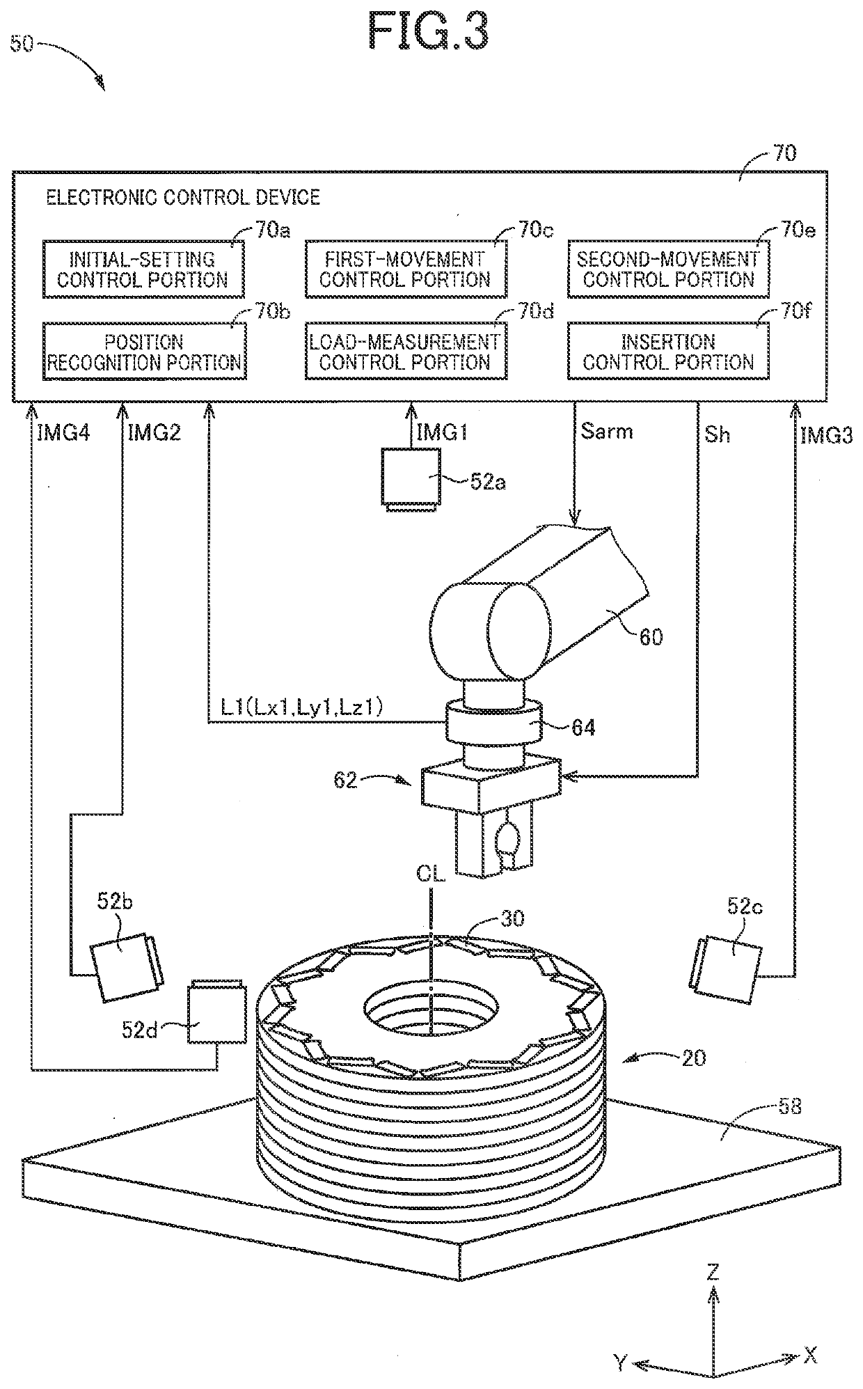
Figure 3
Abstract
Description
[0001] This application claims priority from Japanese Patent Application No. 2020-126886 filed on Jul. 27, 2020, the disclosure of which is herein incorporated by reference in its entirety.FIELD OF THE INVENTION
[0002] The present invention relates to a method of assembling a rotor for an embedded-magnet-type rotating electric machine including a permanent magnet, and also to a control device for a rotor assembly apparatus.BACKGROUND OF THE INVENTION
[0003] There is known a rotor including a rotor core and a permanent magnet which is inserted into a hole portion provided in the rotor core and which is fixed in the hole portion by an adhesive or the like. A rotor disclosed in WO2014 / 178246 A1 is an example of such a rotor. This Japanese Patent Publication describes a method of assembling of the rotor in which the permanent magnet is positioned by a jig and is then inserted into the hole portion.SUMMARY OF THE INVENTION
[0004] By the way, when the permanent magnet is to be inserted into the ...
Examples
first embodiment
[0039]FIG. 1 is a cross sectional view for explaining a construction of a rotor 10 to which the present invention is applied, wherein the cross sectional view is taken in a plane perpendicular to an axis (center line) CL of the rotor 10. Hereinafter, a direction parallel to the axis CL will be simply referred to as “axis CL direction”.
[0040]The rotor 10 is to be provided in a vehicle rotating electric machine MG that is installed in a hybrid vehicle or an electric vehicle so as to serve as a drive power source for driving the vehicle. The vehicle rotating electric machine MG is a rotating electric machine having a function serving as a motor and a function serving as a generator. That is, the vehicle rotating electric machine MG is a so-called motor generator. The vehicle rotating electric machine MG is an embedded-magnet-type rotating electric machine, and includes a stator (not shown) provided with an excitation winding coil, in addition to the rotor 10 in which permanent magnets ...
second embodiment
[0093]FIG. 6 is a view for explaining a construction of a rotor assembly apparatus 150 that is to be used in a method of assembling the rotor, which is according to a second embodiment of the present invention, and also for explaining major portions of control functions that are provided to perform various control operations in the rotor assembly apparatus 150. The rotor assembly apparatus 150 is substantially the same in construction as the rotor assembly apparatus 50 in the above-described first embodiment, but is different from the rotor assembly apparatus 50 in that the table 58 and the load sensor 64 are replaced by a table 158 and a load sensor 164, respectively. In the following description of this second embodiment, there will be described mainly elements different from those of the first embodiment. The same reference signs as used in the first embodiment will be used in the following second embodiment, to identify the functionally corresponding elements, and descriptions t...