
Microcontroller, switched-mode power supply, ballast for operating at least one electric lamp, and method of operating at least one electric lamp
a microcontroller and switched-mode power supply technology, applied in the direction of instruments, light sources, lighting apparatus, etc., can solve the problems of inability to carry out finely graduated pulse-width modulation control nor any finely graduated frequency control of the inverter, and the frequency of the control signal which can be generated by the counting mechanism explained above, etc., to achieve the effect of saving components
Patent Information
- Authority / Receiving Office
- US · United States
- Patent Type
- Patents(United States)
- Current Assignee / Owner
- Publication Date
- 2004-04-06
- Estimated Expiration
- Not applicable · inactive patent
Smart Images
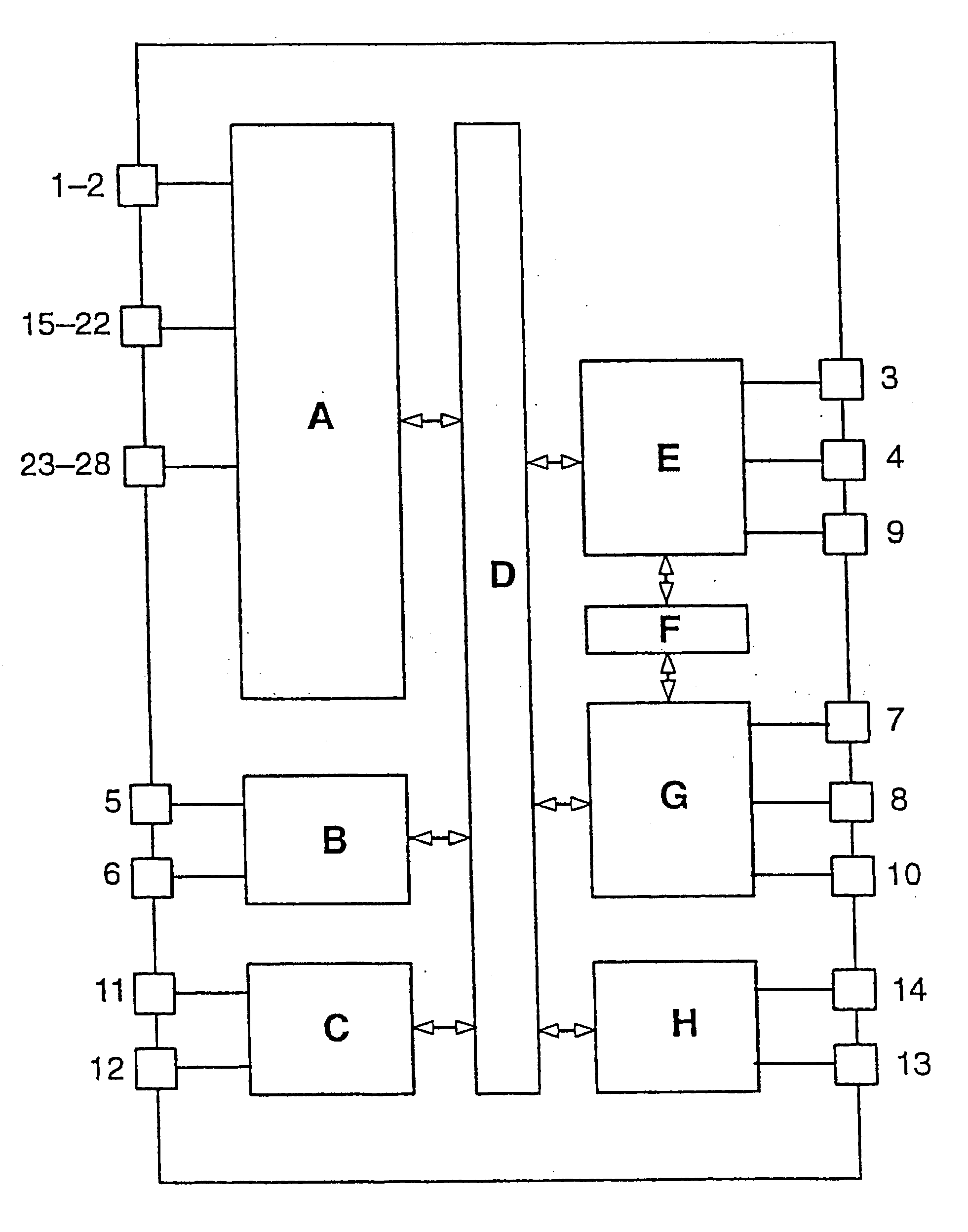
Figure 1 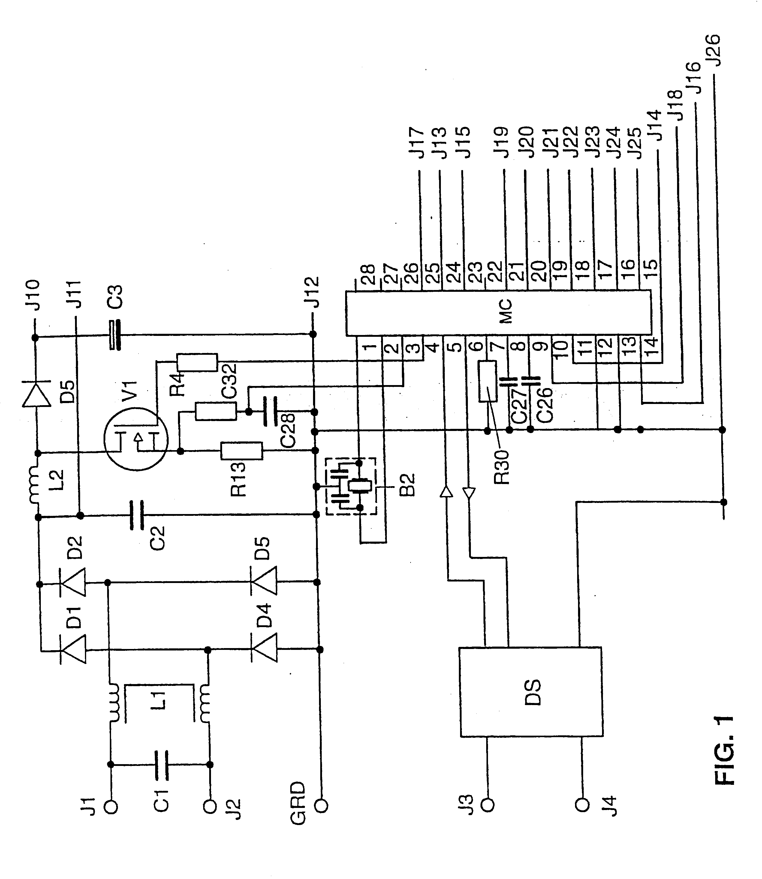
Figure 2 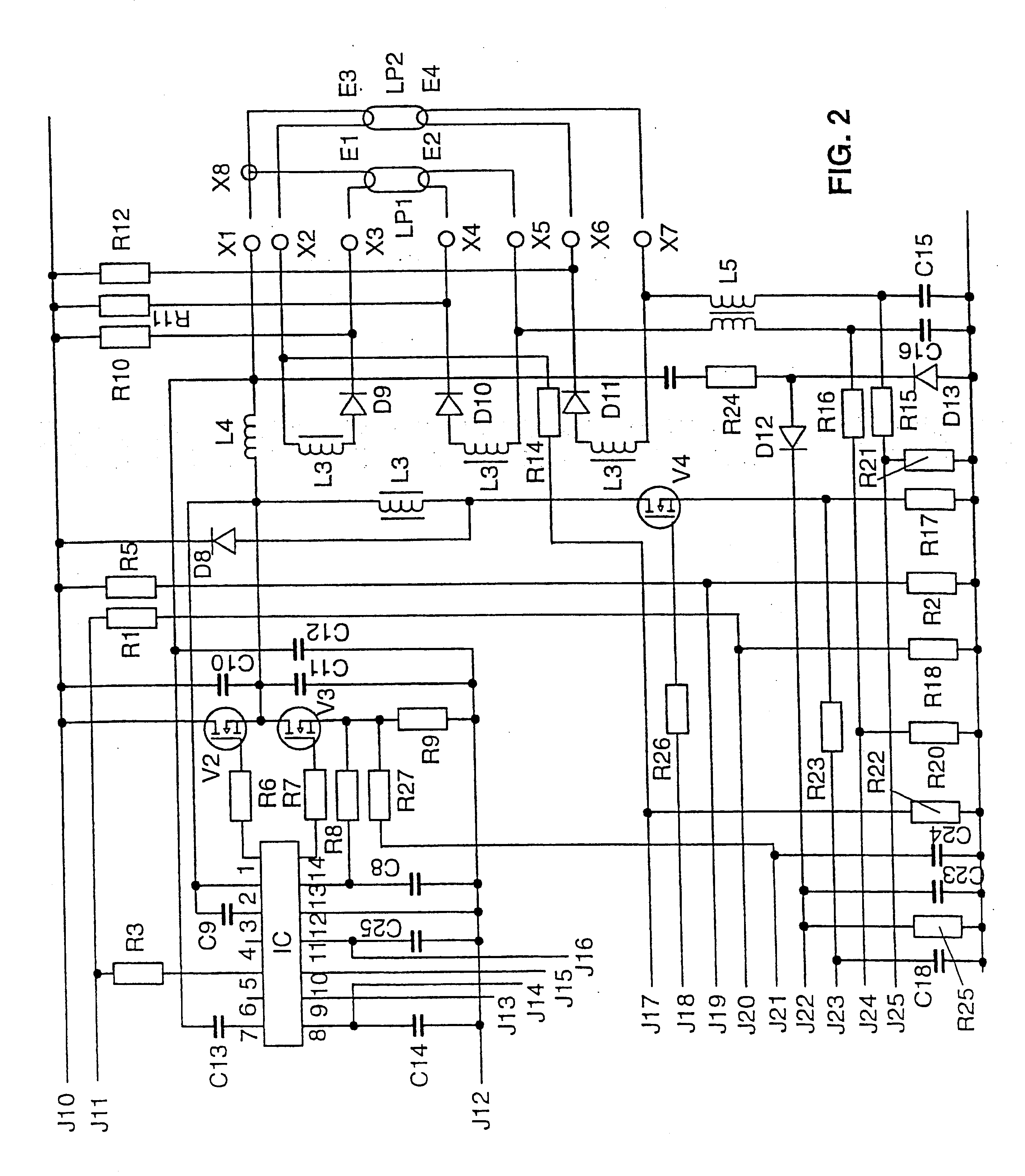
Figure 3
Abstract
Description
The invention relates to a microcontroller according to the preamble of patent claim 1, a switched-mode power supply according to patent claim 10, a ballast for at least one electric lamp according to the preamble of patent claim 11, and a method of operating at least one electric lamp according to the preamble of patent claim 25.I. TECHNICAL FIELDIn particular, the invention relates to a microcontroller which is provided to drive the switching transistors of a switched-mode power supply, to be specific preferably of a switched-mode power supply for operating electric lamps. In the switched-mode power supplies normally used to operate electric lamps, there are normally inverters, in particular half-bridge, full-bridge and push-pull inverters, and also step-up converters and step-down converters. Modern electronic ballasts for operating electric lamps generally have an inverter to produce a high-frequency alternating current for lamp operation and often also have a step-up converter ...
Examples
Embodiment Construction
The circuit arrangement of the preferred exemplary embodiment of the ballast according to the invention is illustrated schematically in FIGS. 1 and 2. Because of its size, the circuit arrangement has had to be illustrated on two sheets. The two halves of the circuit arrangement, depicted in FIGS. 1 and 2, are linked to each other at the connecting points designated by J10 to J26. This ballast is an electronic ballast, as it is known, for operating fluorescent lamps. The ballast has two mains voltage terminals J1, J2, to which a filter circuit, comprising the capacitor C1 and the transformer L1, is connected to suppress radio interference from the ballast. This filter circuit is connected to a bridge rectifier, which is formed by four rectifier diodes D1, D2, D3 and D4. Connected downstream of the bridge rectifier D1-D4 is the capacitor C2, which forms the DC output of the bridge rectifier D1-D4. Connected to the capacitor C2 is a step-up converter, which comprises the field effect t...