
Adjustable support assembly
a technology of supporting assembly and adjustable structure, which is applied in the direction of machine supports, manufacturing tools, washstands, etc., can solve the problems of frequent attention and rendered their use less than fully convenient, and achieve the effect of simple and reliable tools and effectively solving tedious and cumbersome tasks
Patent Information
- Authority / Receiving Office
- US · United States
- Patent Type
- Patents(United States)
- Current Assignee / Owner
- Publication Date
- 2006-11-28
- Estimated Expiration
- Not applicable · inactive patent
Smart Images
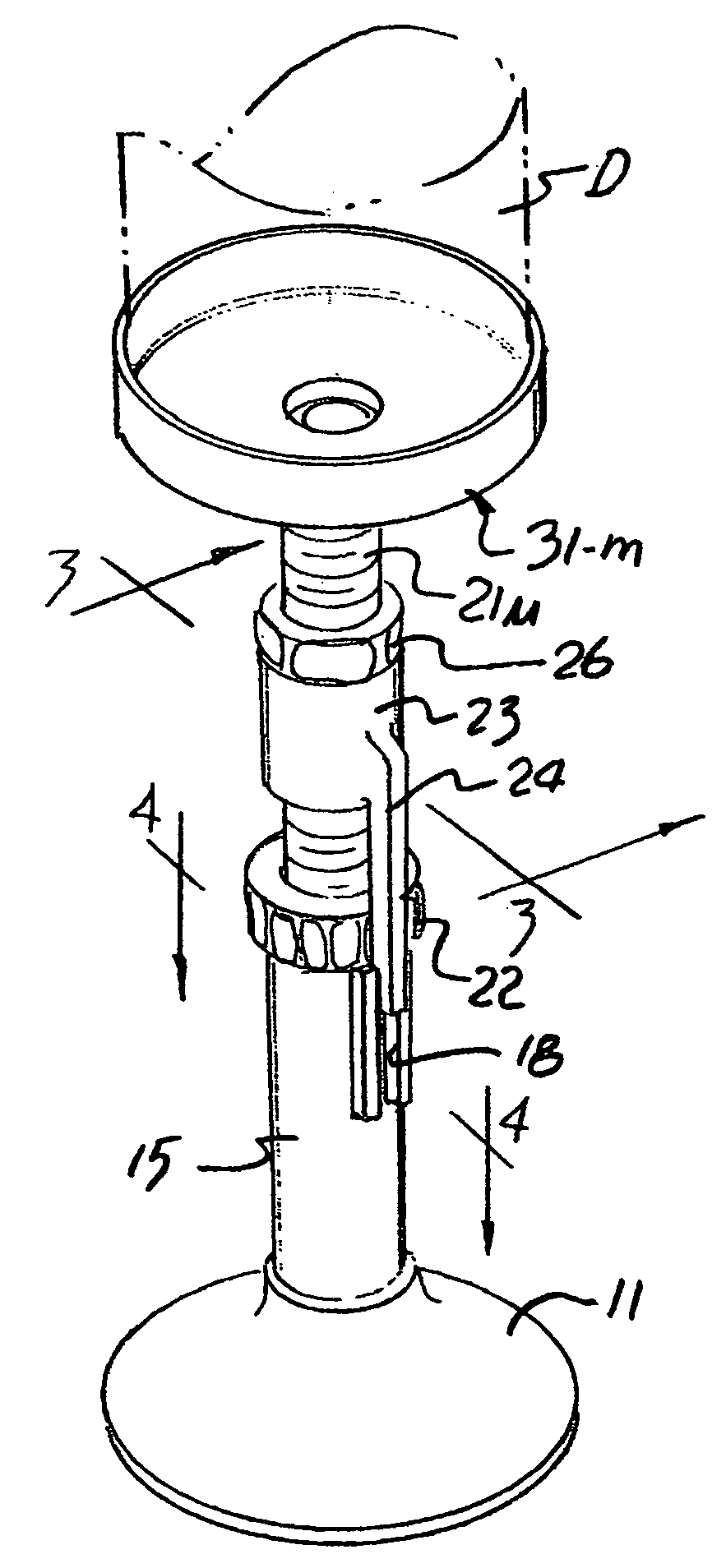
Figure 1 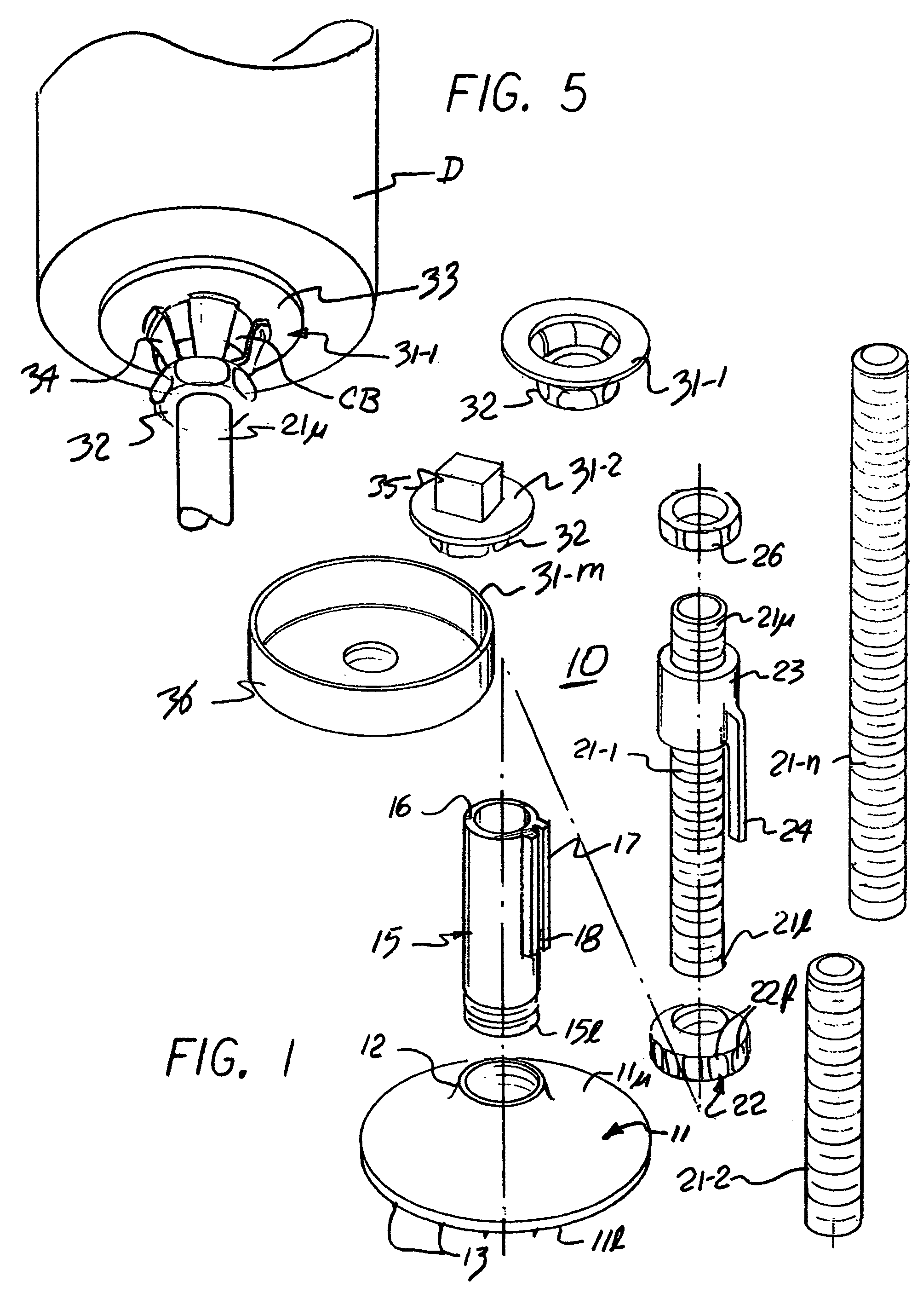
Figure 2 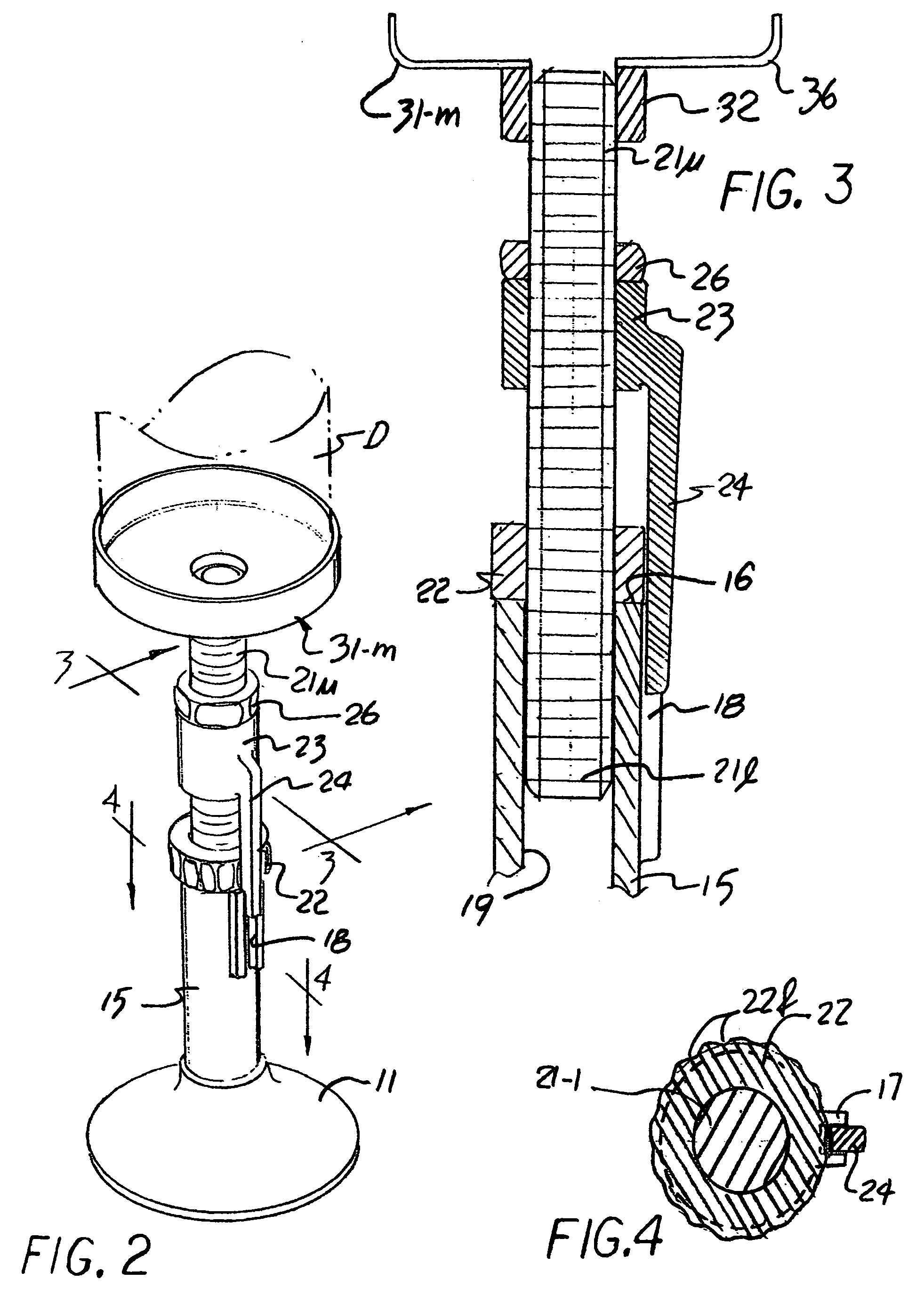
Figure 3
Abstract
Description
REFERENCE TO RELATED APPLICATIONS
[0001] This application is a continuation-in-part of U.S. patent application Ser. No. 10 / 843,602 filed on May 11, 2004 now U.S. Pat. No. 7,024,743 and the benefit of this earlier filing date is claimed for all matter common with this parent application.BACKGROUND OF THE INVENTION
[0002] 1. Field of the Invention
[0003] The present invention relates to tools useful in plumbing assembly, and more particularly to manually adjustable structures insertable under the free edges of a cantilevered sinks and the like while plumbing connections are effected to the drain openings thereof.
[0004] 2. Description of the Prior Art
[0005] The plumbing connection below a sink often include complex geometries confined in a small space that are sometimes compounded by items like a food debris macerators, or garbage disposal, in current implementation comprises an electromechanical structure of some bulk and mass. While many improvements have made to render these devices and the...
Examples
Embodiment Construction
[0021]As shown in FIGS. 1–4, the inventive support assembly, generally designated by the numeral 10, comprises a base 11 of a generally planar configuration provided with a threaded boss 12 on the upper surface 11u thereof. The peripheral edge surface of the lower surface 11l may be finished to a rough finish, shown by projections 13, to increase frictional resistance to any rotary displacement thereof A pipe segment 15 exteriorly threaded over the lower end surface 15l is then threadably insertable into the boss 12 to form a vertically aligned annular structure supported on the base and defined at the upper end 15u by a smoothed end surface 16. A longitudinally aligned channel piece 17 is then affixed to the outer surface of segment 15 to present a radially directed recess 18 extending from surface 16 along a portion of segment 15.
[0022]A selected one of a plurality of threaded rods 21-1 through 21-n, shown as rod 21-1 in the Figure, is then threadably received in the interior of a...