
Method for navigating in the interior of the body using three-dimensionally visualized structures
a three-dimensional visualization and interior technology, applied in the field of interior navigation using three-dimensional visualization structures, can solve the problems of difficult surgery for surgeons, often even impossible to optically survey the anatomical structure of patients, and insufficient two-dimensional images such as x-ray images, and achieve the effect of facilitating the alignment of the effective axis
Patent Information
- Authority / Receiving Office
- US · United States
- Patent Type
- Patents(United States)
- Current Assignee / Owner
- Publication Date
- 2007-01-23
Smart Images
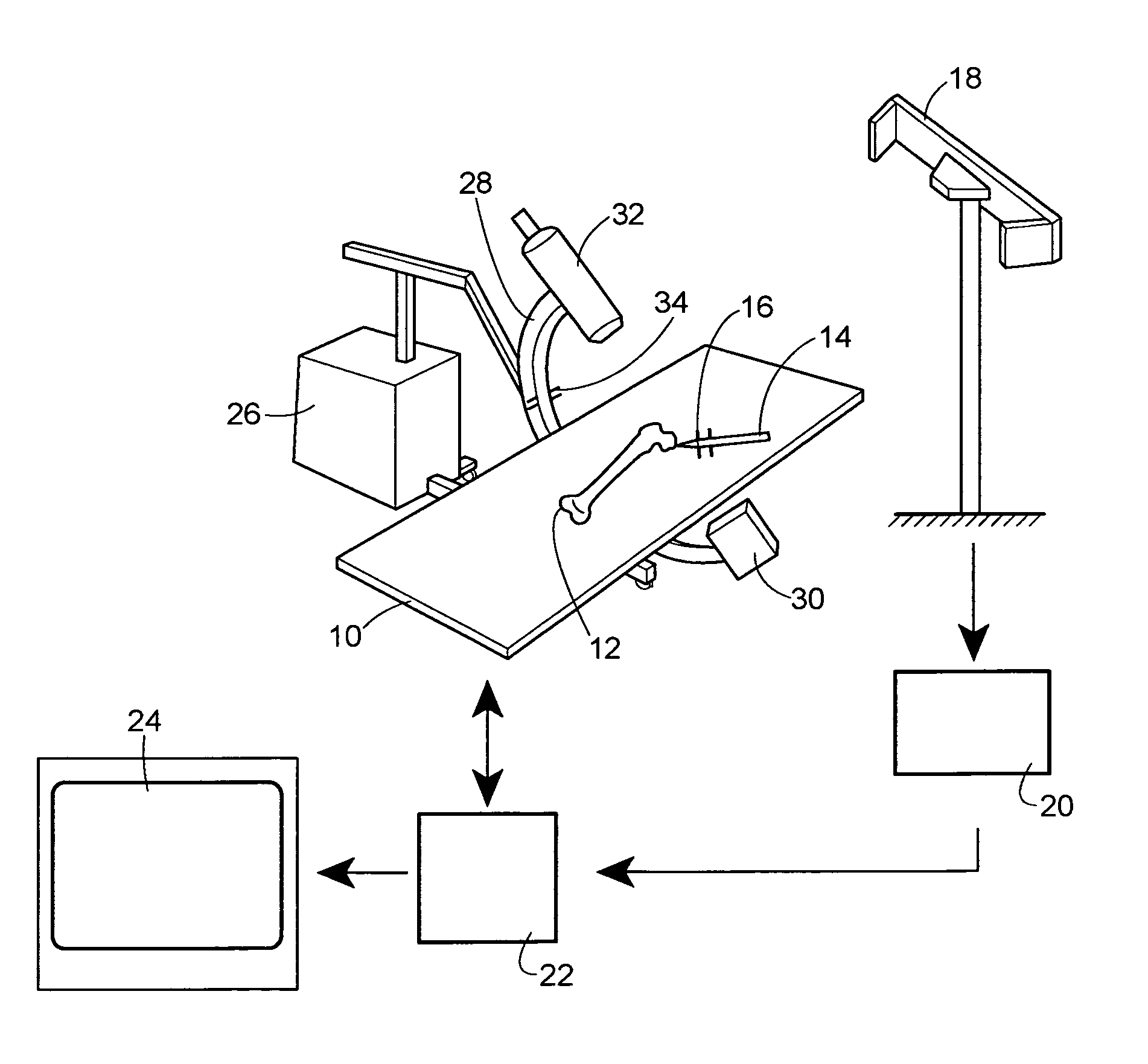
Figure 1 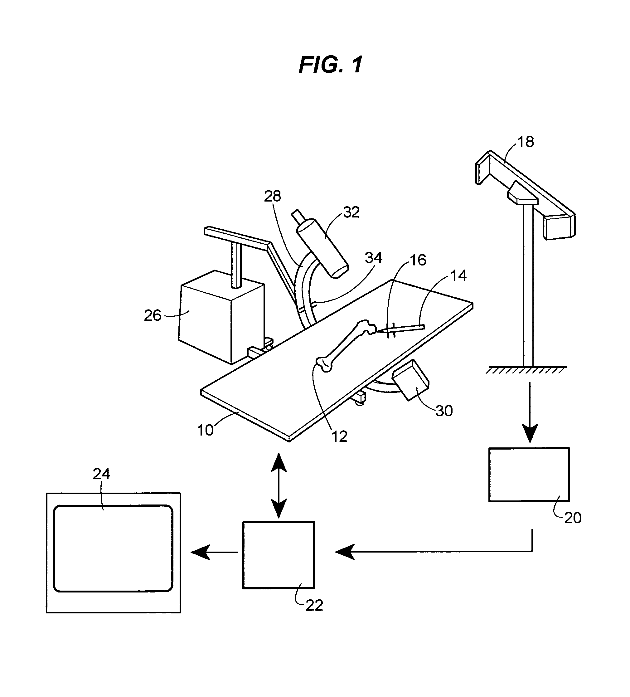
Figure 2 
Figure 3
Abstract
Description
[0001] This application is a 371 pf PCT / EP01 / 08844 filed Jul. 31, 2001.BACKGROUND OF THE INVENTION
[0002] The invention relates to a method for navigating, for example a surgical instrument or an endoscope, in the interior of the body using three-dimensionally visualized structures.
[0003] During surgical operations, an attempt is made, as a rule, to make as small a cut as possible through the skin of the patient. Said cut is often just big enough in order to be able to reach the anatomical structure to be treated in the interior of the body with surgical instruments. For this reason, it is difficult for the surgeon and often even impossible to survey optically those anatomical structures of the patient that are relevant to the operation. Even the position, for example, of surgical instruments relative to an anatomical object to be treated is often not visible to the surgeon. For this reason, methods of visualizing structures in the interior of the body for the purpose of navigating such...
Examples
Embodiment Construction
[0040]FIG. 1 shows diagrammatically an operation scenario based on the visualization method according to the invention. Disposed on an operating table 10 is an anatomical object to be treated operatively in the form of a femur bone 12. The surgical intervention is performed with the aid of a surgical instrument 14. Attached to the surgical instrument 14 is a marker 16 of an infrared tracking system. Said marker 16 is designed to transmit infrared radiation. The infrared tracking system comprises, furthermore, an infrared detector 18 disposed in a positionally fixed manner. A localization computer 20 of the tracking system calculates the actual spatial position of the surgical instrument 14 provided with the marker 16 from the signals received by the infrared detector 18. The calculated spatial co-ordinates are transmitted by the localization computer 20 via a data bus to a central computer 22, where they are processed graphically and represented graphically on a viewing screen 24.
[0...