
Image processing device
a technology of image processing which is applied in the field of image processing device and image processing program, can solve the problems of generating recurrent patterns, wasting resources, and wasting resources,
Patent Information
- Authority / Receiving Office
- US · United States
- Current Assignee / Owner
- Publication Date
- 2008-11-04
Smart Images
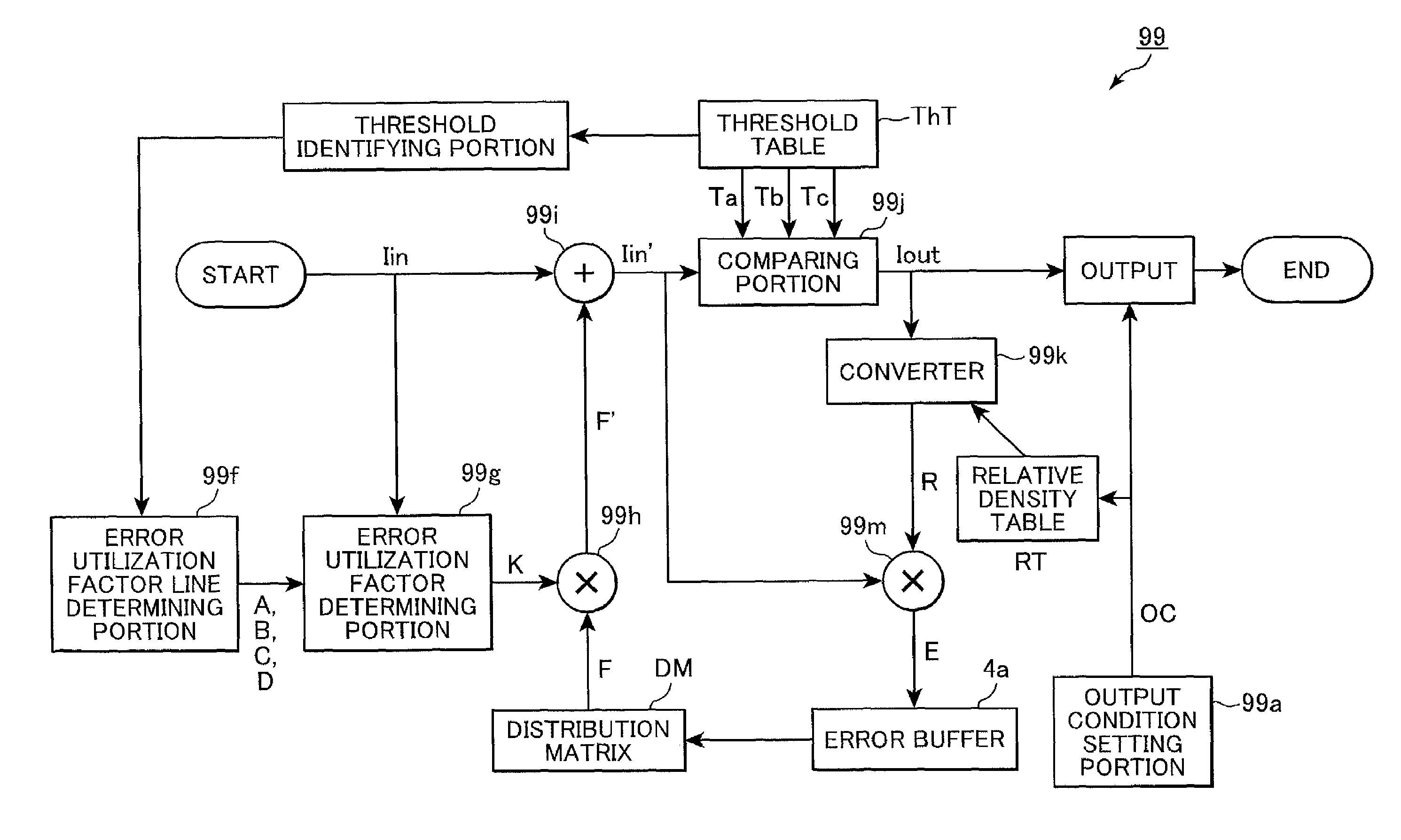
Figure 1 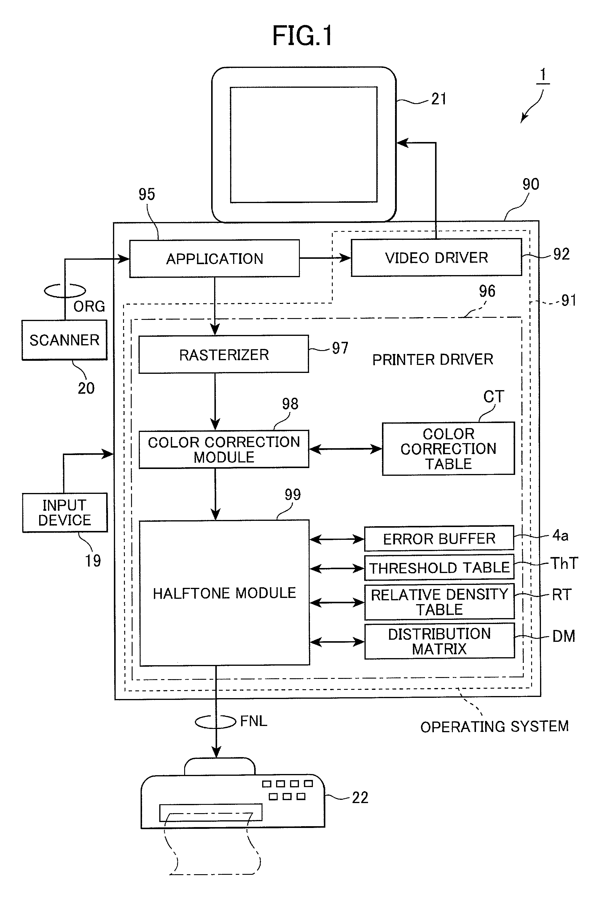
Figure 2 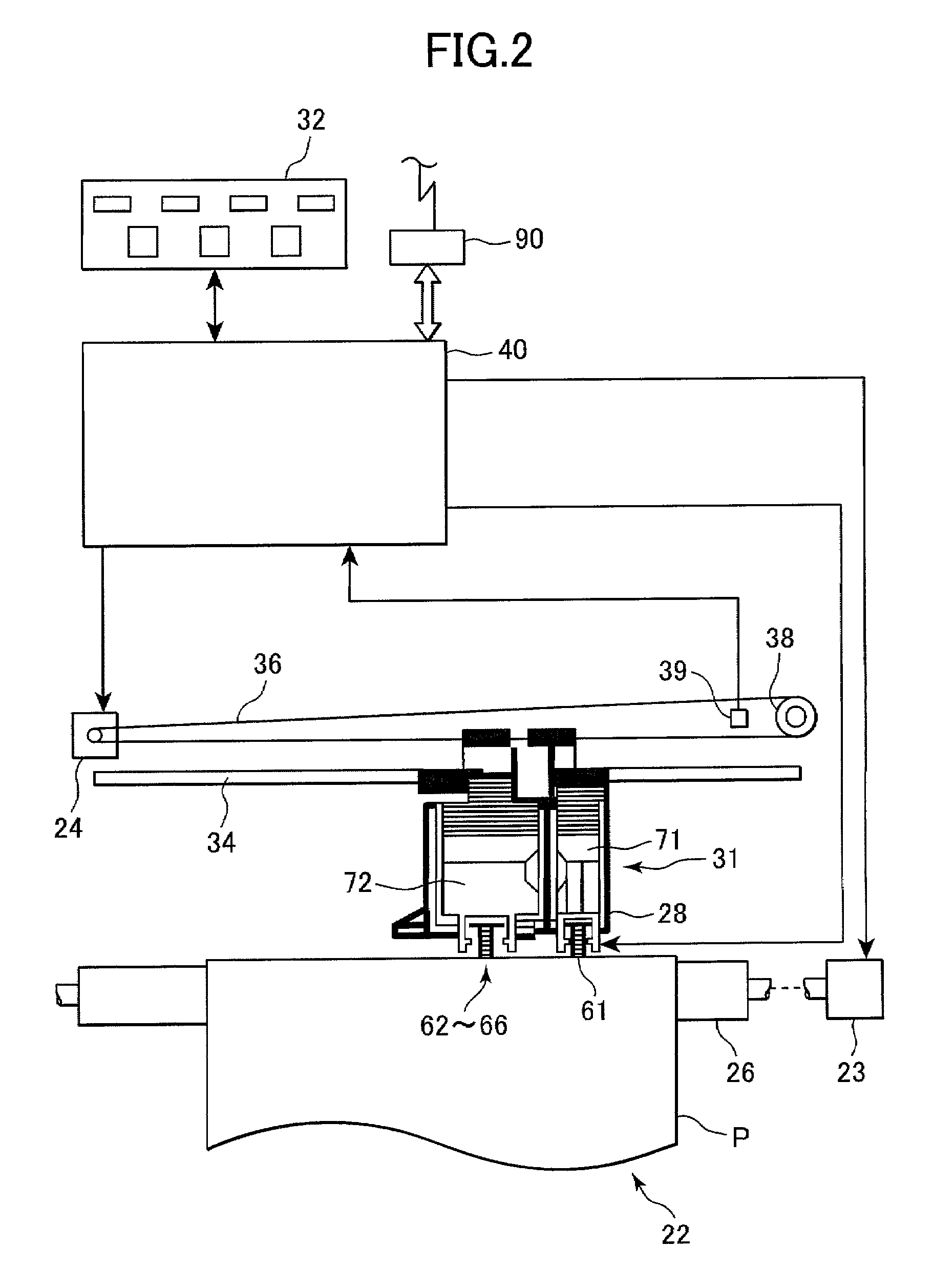
Figure 3
Abstract
Description
BACKGROUND OF THE INVENTION
[0001] 1. Field of the Invention
[0002] The present invention relates to an image processing device and an image processing program for rapidly processing image data and rendering advanced gradations.
[0003] 2. Description of Related Art
[0004] In recent years, color printers of the type that eject multiple colors of ink from the print head, commonly known as inkjet printers, have become widely popularized as a computer output device. These inkjet printers are widely used to print images that have been processed by a computer or the like in multiple colors and multiple gradations. The color printer renders gradations according to a halftone process that distributes dots according to inputted gradation data.
[0005] One method of this halftone process is the error diffusion method. Currently, the error diffusion method is the method most commonly used to reproduce high quality images. To describe the process more specifically, the differences between input values and...
Examples
first embodiment
[0049]FIG. 1 shows the configuration of an image processing system 1 according to a first embodiment of the present invention. The image processing system 1 is constructed from: a personal computer 90, which is the image processing device of the present embodiment; and a color printer 22 which is an image forming device outputting an image processed by the personal computer 90.
[0050]As shown in FIG. 1, the image forming system 1 includes the personal computer 90 and, provided external to the personal computer 90, a scanner 20, the color printer 22, a color display 21, and an input device 19 such as a keyboard, mouse, and the like.
[0051]The external scanner 20 reads color image data from an original color print and supplies original color image data ORG to the personal computer 90. The original color image data ORG includes three color components: red (R), green (G), and blue (B).
[0052]When desiring to print images, the personal computer 90 generates, based on the original color imag...
second embodiment
[0163]Next will be described a second embodiment of the present invention with reference to FIGS. 9, 13, 14, 15(A), and 15(B).
[0164]As shown in FIG. 13, according to the present embodiment, the halftone module 99 is not provided with the image characteristic identifying portion 99b, but is provided with a recording characteristic identifying portion 99c. The recording characteristic identifying portion 99c is for identifying recording characteristics of the printer 22 based on the output conditions OC set by the output condition setting portion 99a. The error utilization factor line determining portion 99f determines characteristic values A, B, C, and D for each color component based on the identified recording characteristics.
[0165]Similarly to the first embodiment, the recording characteristic identifying portion 99c and the error utilization factor line determining portion 99f cooperate to determine the characteristic values A, B, C, and D and the error utilization factor line of...
first modification
of Second Embodiment
[0176]A first modification of the present embodiment will be described with reference to FIGS. 9, 13, and 16(A).
[0177]In this modification, the recording characteristic identifying portion 99c identifies, as the recording characteristics, printing resolution set for the present printing operation. The error utilization factor line determining portion 99f determines characteristic values A, B, C, and D for each color component based on the printing resolution.
[0178]According to the present modification, the hard disk device 10 previously stores therein a printing resolution-characteristic table PRT shown in FIG. 16(A). The printing resolution-characteristic table PRT lists up the characteristic values A, B, C, and D for each of several printing resolutions (200×200 and 800×800, in this example).
[0179]It is noted that humans perceive dots differently based on different printing resolutions. Accordingly, characteristic values A, B, C, and D are determined is beforeh...