
Lens driving apparatus, imaging apparatus, and lens barrel and camera main body used for this
a driving apparatus and lens barrel technology, applied in the field of imaging apparatus, can solve the problems of difficult to achieve suitable performance for realizing high-quality images, disadvantageous in terms of compact size and cost, and difficult to realize compact lens barrel and low cost, and achieve smooth origin detection and precise alignment control. , the effect of low cos
Patent Information
- Authority / Receiving Office
- US · United States
- Patent Type
- Patents(United States)
- Current Assignee / Owner
- Publication Date
- 2009-08-11
- Estimated Expiration
- Not applicable · inactive patent
Smart Images
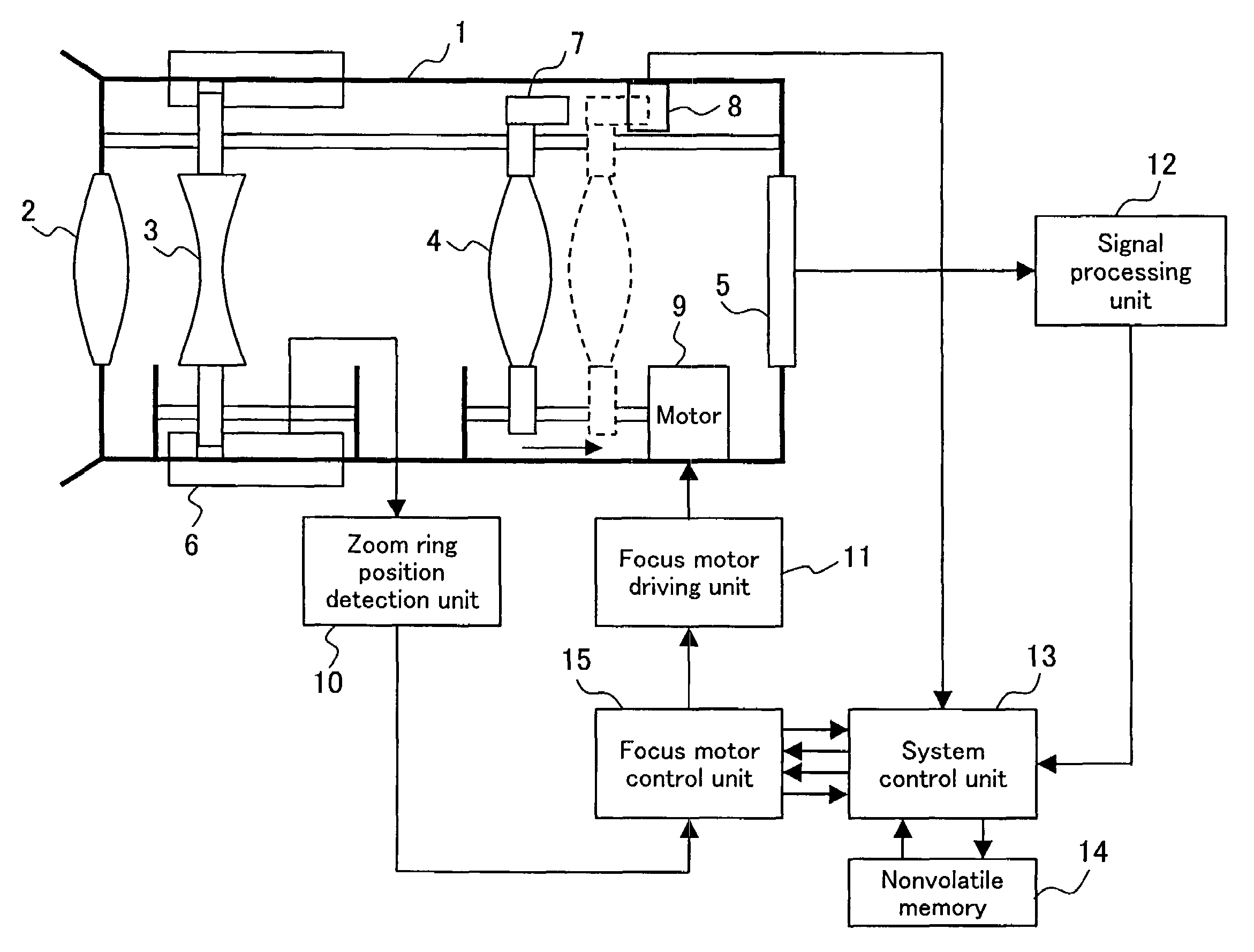
Figure 1 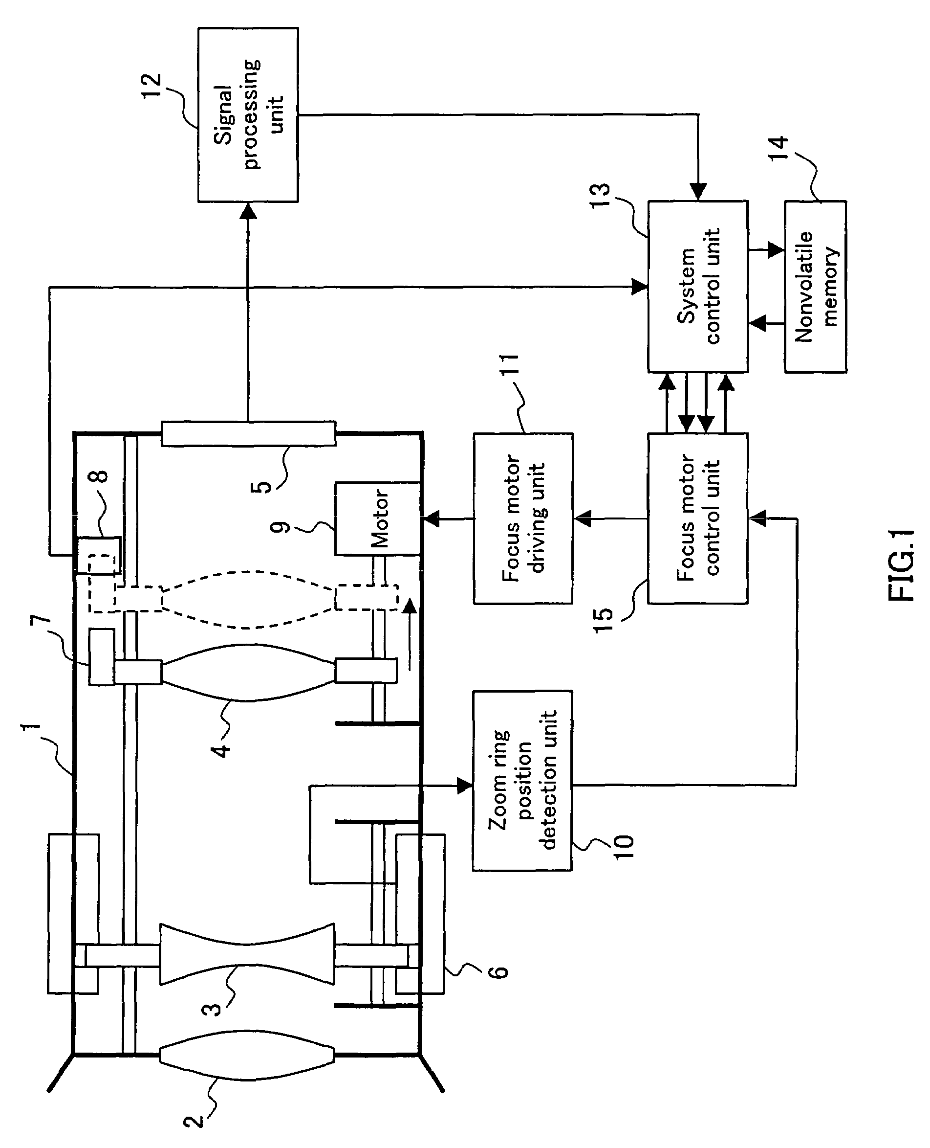
Figure 2 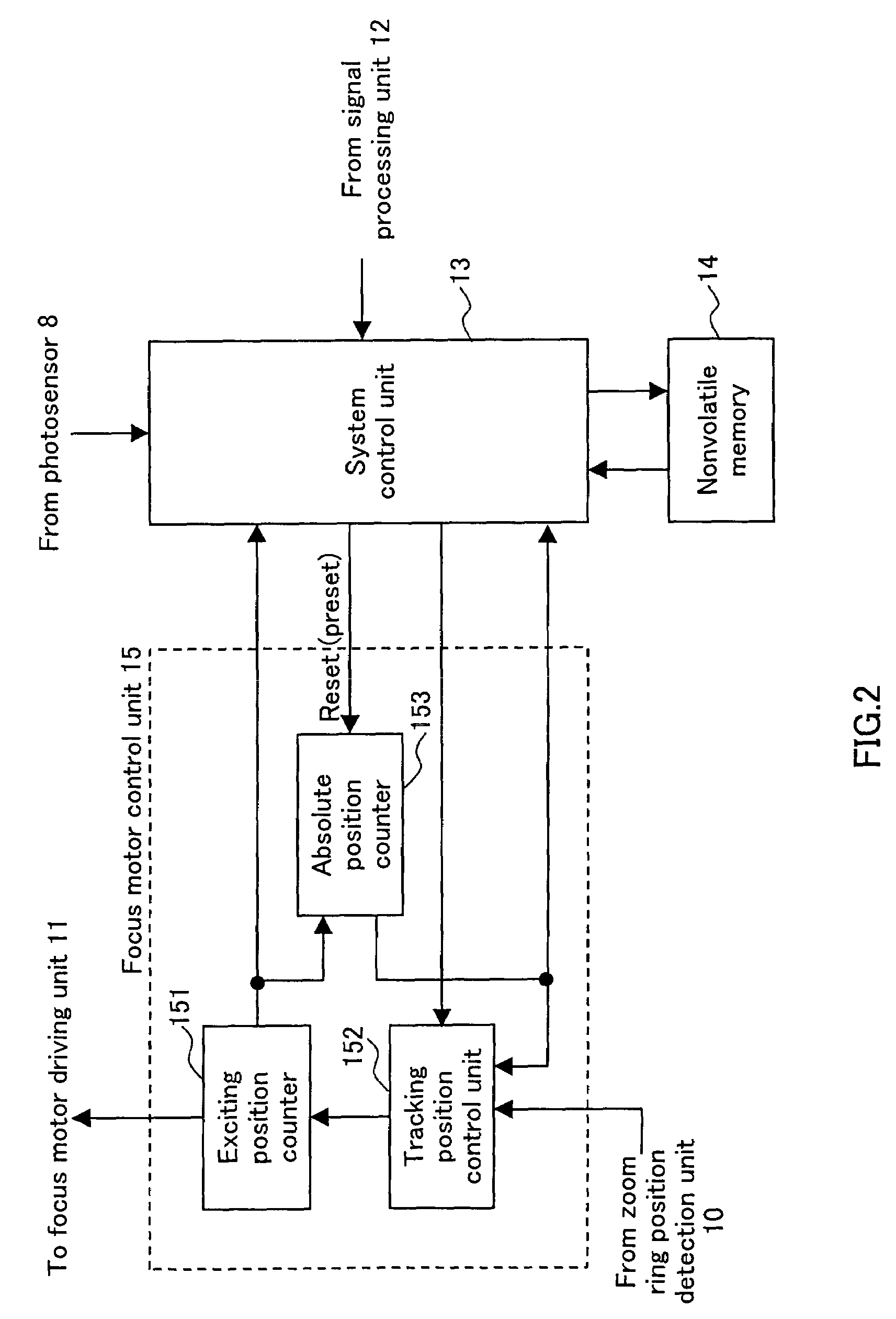
Figure 3
Abstract
Description
TECHNICAL FIELD
[0001] The present invention relates to an imaging apparatus such as a still camera or a video movie, a lens driving apparatus that controls a position of a lens of such an apparatus and relates to a lens barrel and a camera main body used for an imaging apparatus.BACKGROUND ART
[0002] Conventionally, a method for detecting the origin of a lens unit is proposed in which when the lens unit is driven by a motor, a photo-interruption member attached to the lens unit and a photosensor are used so as to monitor an output level of the photosensor at the time when the photo-interruption member transverses the photosensor (Patent Document 1, for example).
[0003] A conventional lens driving apparatus is described below, with reference to FIG. 58. FIG. 58 includes a schematic diagram and a block diagram of an exemplary conventional lens driving apparatus. In an imaging device 75, an image of a subject captured through a fixed lens 72 fixed to a barrel 71, a zoom lens 73 and a focus ...
Examples
embodiment 1
[0177]FIG. 1 includes a schematic diagram and a block diagram of a lens driving apparatus according to Embodiment 1 of the present invention. In FIG. 1, numeral 1 denotes a lens barrel, 2 denotes a fixed lens fixed to the lens barrel 1 and 3 denotes a zoom lens. The zoom lens 3 moves in the optical axis direction so as to adjust a zoom magnification along with the rotation of a zoom ring 6 along the perimeter of the lens barrel 1. Numeral 4 denotes a focus lens. When a motor 9 as a driver rotates, the focus lens 4 moves in the optical axis direction along a lead screw with threads cut therein so as to enable the adjustment of focus.
[0178]In the example of FIG. 1, the motor 9 is a stepping motor that rotates in accordance with a phase of a driving signal (exciting signal) for a motor coil output from a focus motor driving unit 11. Numeral 5 denotes an imaging device that converts an image of a subject captured through the fixed lens 2, the zoom lens 3 and the focus lens 4 into an ele...
embodiment 2
[0214]The following describes Embodiment 2 of the present invention. Embodiment 2 is the same as in Embodiment 1 in the configuration shown in FIG. 1 and FIG. 2 and the origin detection operation during the process adjustment described referring to FIG. 3 and FIG. 4.
[0215]Referring now to FIGS. 8 and 9, the origin detection operation of a focus lens 4 during the normal operation in Embodiment 2 is described below. FIG. 8 is a drawing for explaining the origin detection operation during the normal operation according to Embodiment 2. Since the exciting position, the A-phase current, the B-phase current, the absolute position counter and the photosensor output level shown in FIG. 8 are the same as those described in FIG. 3, the duplicate explanations are omitted.
[0216]Embodiment 2 is different from Embodiment 1 in that the exciting position is decreased by two at one time when the focus lens 4 is shifted to the imaging device 5 side. Therefore, an absolute position counter 153, which ...
embodiment 3
[0226]The following describes Embodiment 3 of the present invention. In the following description, duplication of the configurations shown in FIG. 1 and FIG. 2 described in Embodiment 1 is omitted. Embodiment 3 explains the example where the focus motor driving unit 11 of FIG. 1 drives the motor 9 to rotate by substantially sine wave driving (called also microstep driving). Further, the exciting position counter 151 of FIG. 2 is a 5-bit counter that comes full circle with the counter value of 32 representing one cycle (360 degrees) of the driving electrical angle of the motor 9. The absolute position counter 153 operates in synchronization with the counter value of the exciting position counter 151, and is preset or reset under a predetermined condition described later.
[0227]The operation is described below, with reference to FIG. 10. FIG. 10 is a drawing for explaining an origin detection operation during the process adjustment according to Embodiment 3. The “exciting position” sho...