
Chair lift
a technology for lifting devices and chairs, which is applied in the direction of moving seats, transportation and packaging, vehicle arrangements, etc., can solve the problems of difficult activities for many older people and people with physical disabilities, such as the difficulty of getting up out of a chair, the inability of chairs to stand up, and the inability of people with physical disabilities to scoot forward and then stand up from a comfortable chair. achieve the effect of economics and manufacturing
Patent Information
- Authority / Receiving Office
- US · United States
- Patent Type
- Patents(United States)
- Current Assignee / Owner
- Publication Date
- 2011-04-19
- Estimated Expiration
- Not applicable · inactive patent
Smart Images
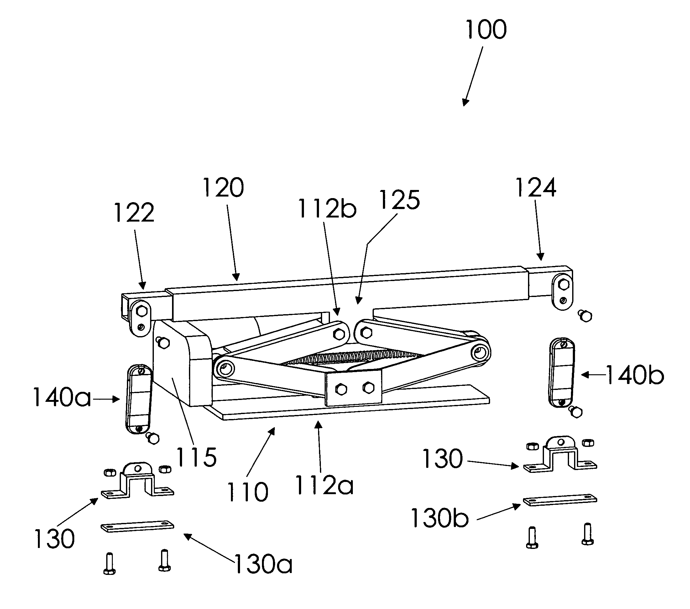
Figure 1 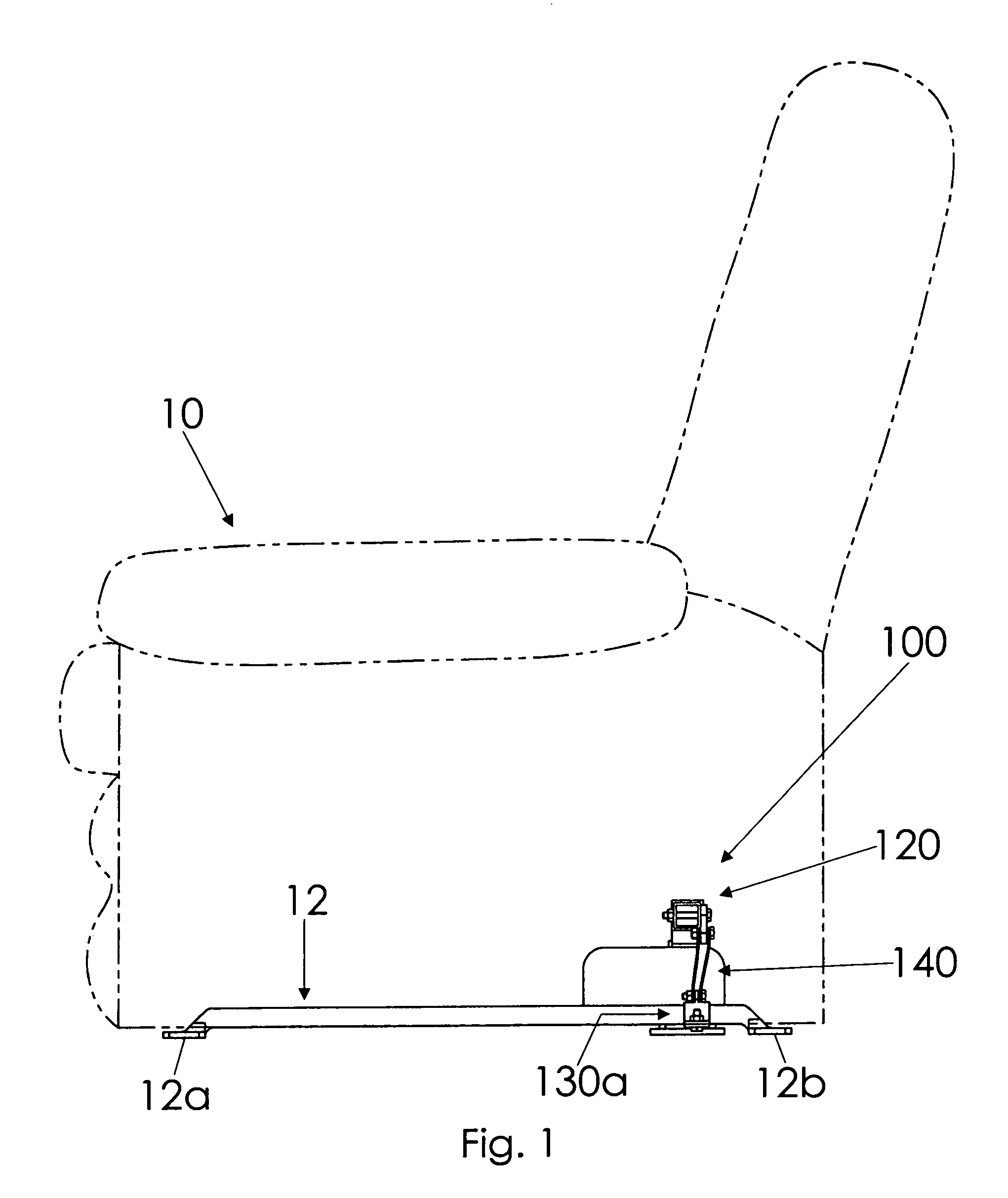
Figure 2 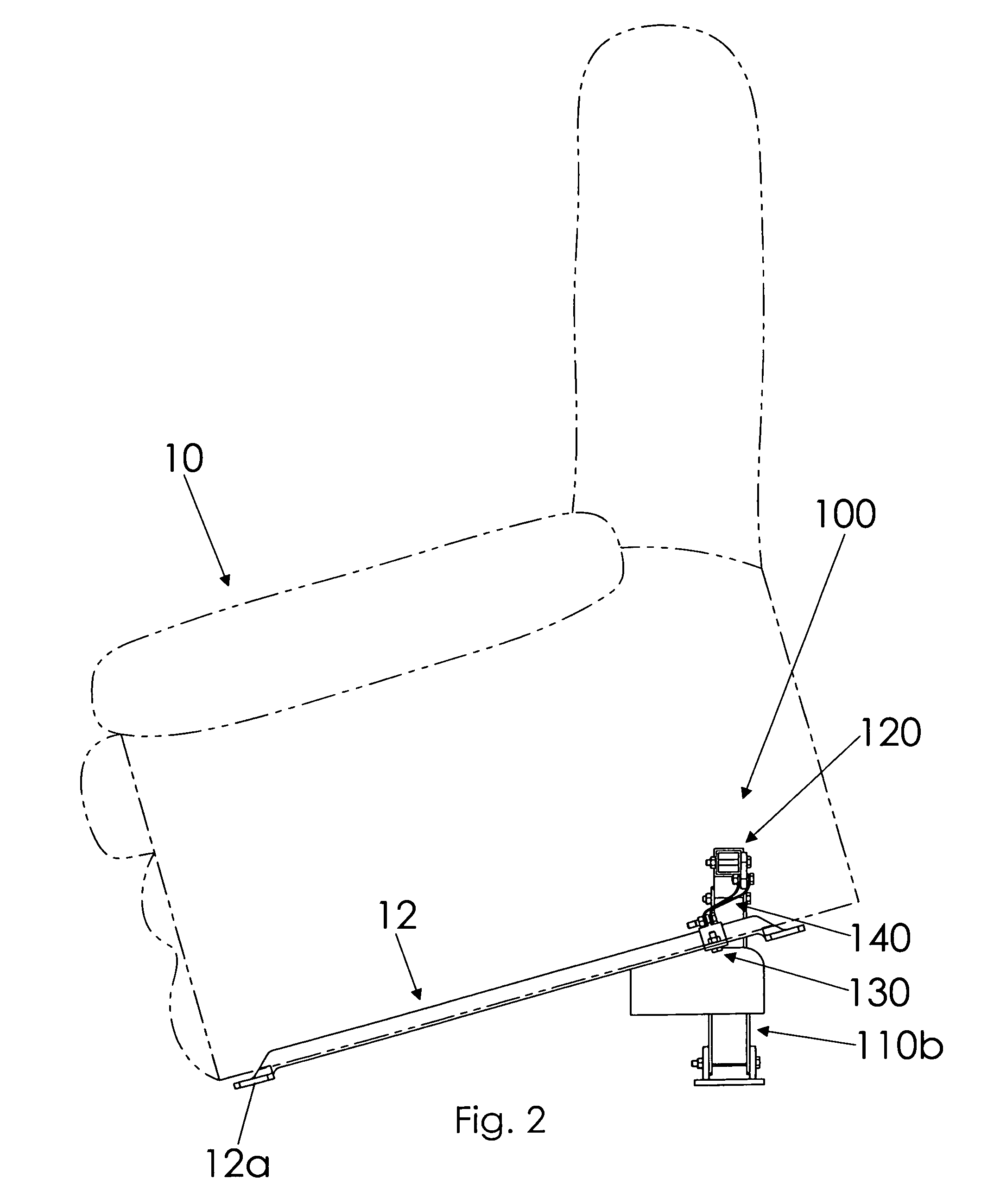
Figure 3
Abstract
Description
BACKGROUND OF THE INVENTION
[0001] This invention relates generally to chair lifting devices and, more particularly, to a chair lift that is attachable to and removable from most reclining chairs and which raises a chair without hampering the basic functions or attractive appearance of the chair.
[0002] One of the most difficult activities for many older people and people with physical disabilities is to get up out of a chair, especially large recliner type chairs. Sometimes the most comfortable chairs in which a person just sinks into are the most difficult chairs to stand up from. A person who lacks physical strength or coordination may find it awkward or even impossible to scoot forward and then stand up from the comfortable chair.
[0003] Various devices have been proposed in the art for lifting or tipping recliner chairs in order to assist persons lacking sufficient physical strength or coordination to rise from the chair without assistance. Although assumably effective for their inte...
Examples
Embodiment Construction
[0023]A chair lift will now be described in detail with reference to FIG. 1 through FIG. 7b of the accompanying drawings. More particularly, a chair lift 100 includes a jack 110, a mounting bracket 120, clamping mechanisms 130, and flexible connecting links 140.
[0024]As shown in FIGS. 5a and 5b, the jack 110 is movable between lowered and raised configurations 110a, 110b. The jack 110 has a lower end 112a adjacent a ground surface and an opposed upper end 112b that may move up and down. A motor 115 is in communication with the jack 110 for moving the jack 110 between the lowered and raised configurations 110a, 110b, and a switch 113 is in communication with the motor 115 to selectively actuate the motor 115. In some embodiments, the user may actuate the switch through a remote control. The jack 110 may be a scissor jack, as shown in FIGS. 5a and 5b, or any other appropriate type of jack.
[0025]The mounting bracket 120 is coupled to the jack 110 to move vertically as the jack 110 move...