
Aircraft fuel pipe coupling
a technology of fuel pipe coupling and fuel pipe, which is applied in the direction of couplings, pipe supports, pipe elements, etc., can solve the problems of increasing seal and coupling wear, limiting the angular deflection allowable, and using flexible couplings
Patent Information
- Authority / Receiving Office
- US · United States
- Current Assignee / Owner
- Publication Date
- 2012-05-08
Smart Images
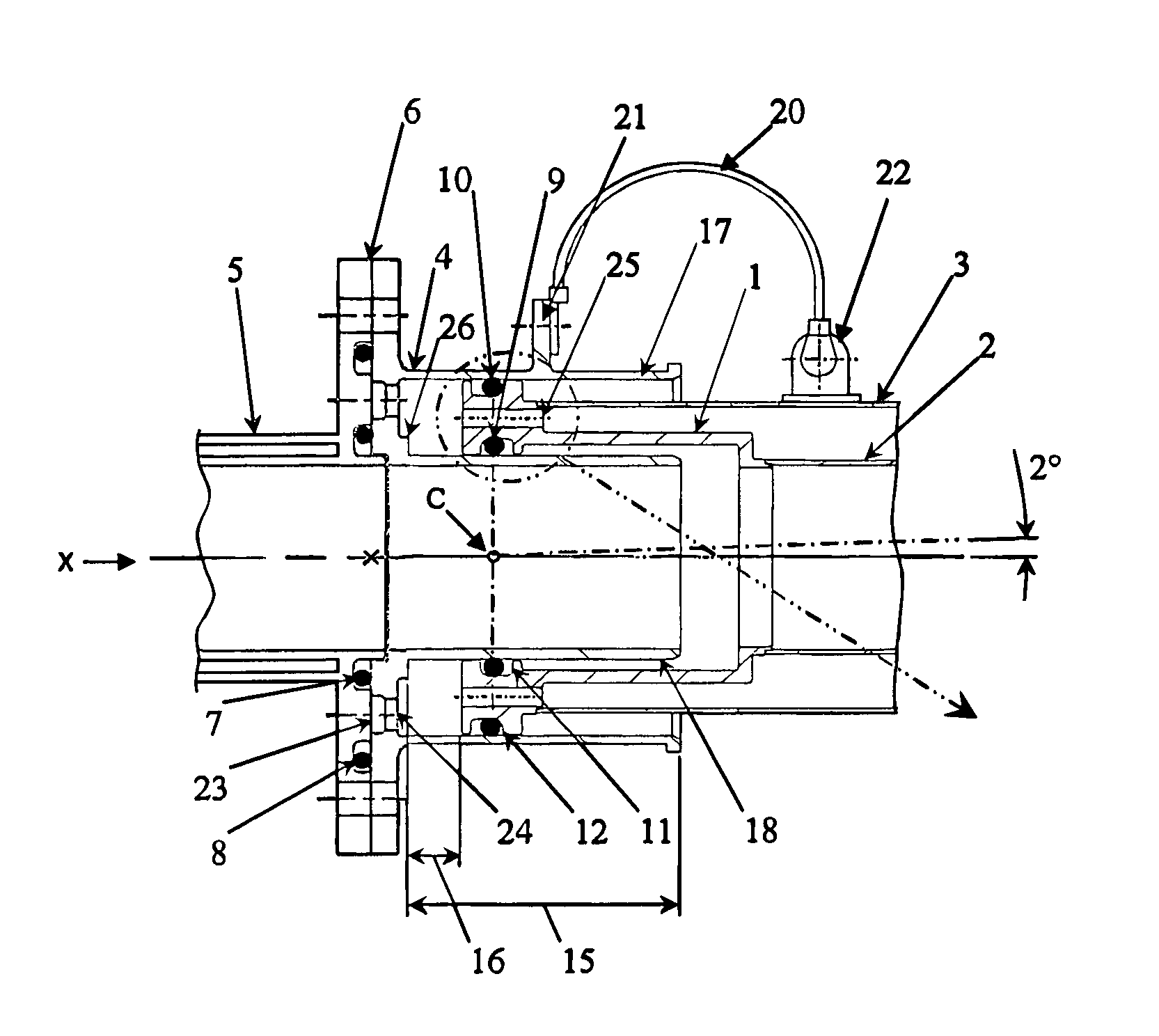
Figure 1 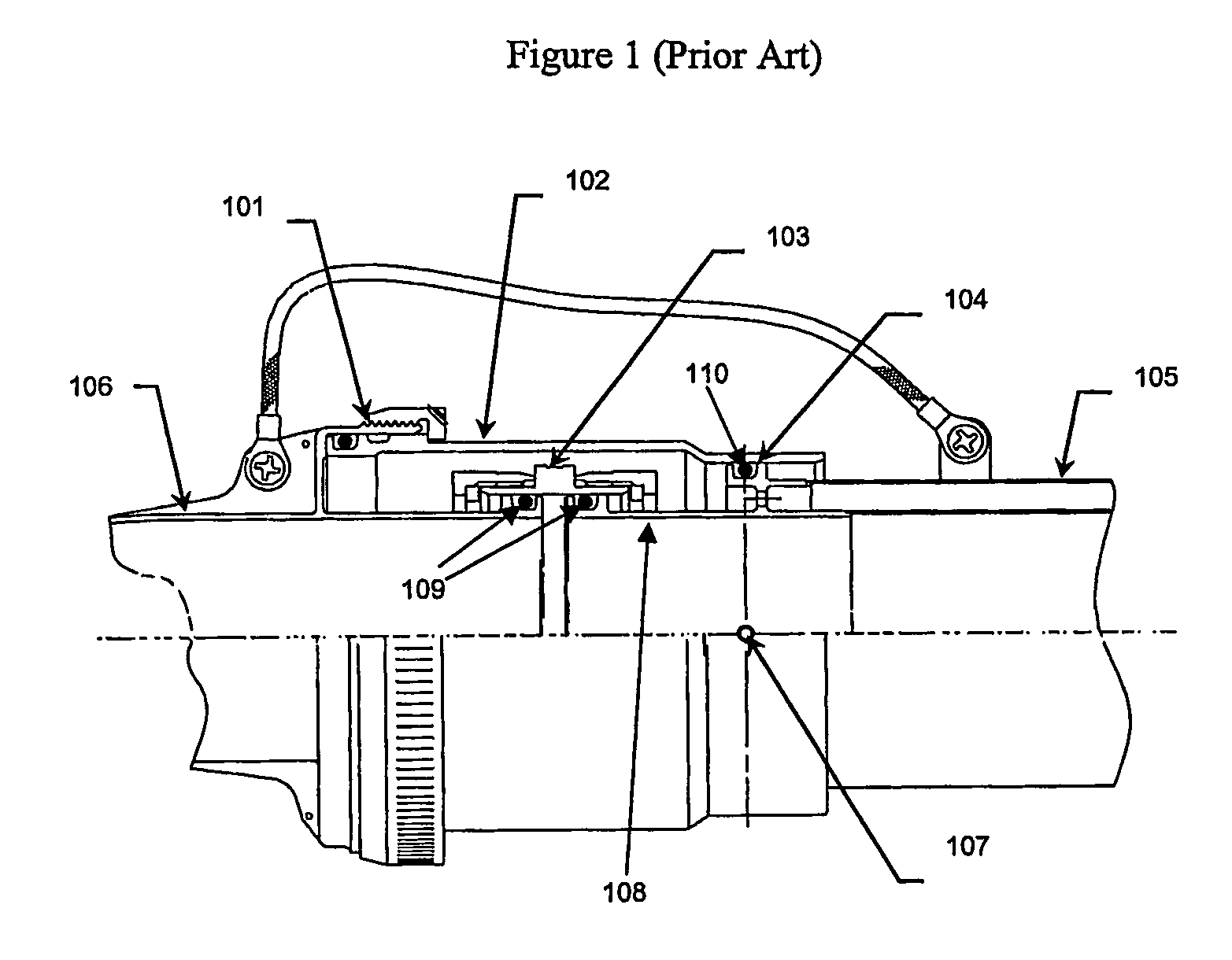
Figure 2 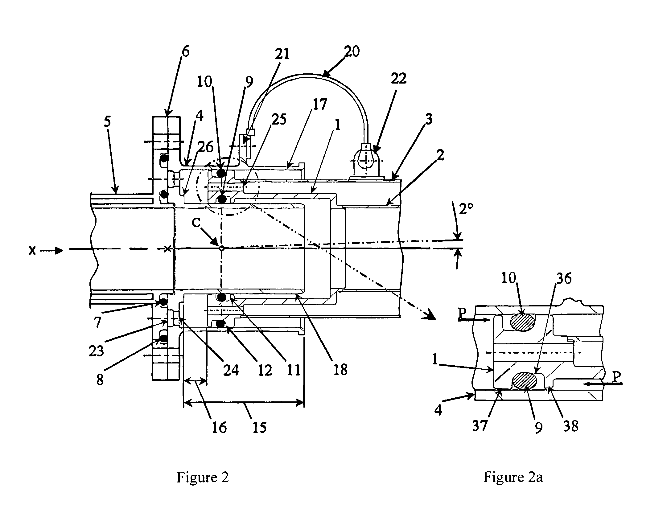
Figure 3
Abstract
Description
[0001] This application is the U.S. national phase of International Application No. PCT / GB2006 / 003744, filed 6 Oct. 2006, which designated the U.S. and claims priority to Great Britain Application No. 0523573.4, filed 18 Nov. 2005, the entire contents of each of which are hereby incorporated by reference.BACKGROUND OF THE INVENTION
[0002] 1. Field of the Invention
[0003] The present invention relates to aircraft fuel pipe couplings and in particular but not exclusively flexible pipe couplings for connecting a double-walled pipe in an aircraft fuel system to another fuel pipe.
[0004] 2. Discussion of Prior Art
[0005] In aircraft fuel systems it is often necessary to use double-walled pipes, connectors and couplings in order to protect from fuel leakage. When the risk of leakage is high, for example in the pressurised fuselage of an aircraft, the entire fuel system may be double-walled. Where the risk of leakage is less, it may only be the couplings that are double-walled. Further complication...
Examples
first embodiment
[0042]FIGS. 2 and 2a show a coupling according to the invention. The coupling is arranged about an axis X and joins a double-walled rigid pipe 5 (on the left in FIG. 2) and a double-walled rigid pipe (on the right in FIG. 2) comprising an inner rigid pipe wall 2 and an outer rigid pipe wall 3. The coupling comprises a unitary end fitting 1 attached by fusion welding to the double-walled pipe 2, 3. The coupling also comprises a unitary double-walled socket 4 attached to the adjacent double-walled pipe 5 by means of a split flange, the split flange comprising a flange on the pipe 5 and a corresponding flange on the double-walled socket 4, the split line indicated by the arrow 6. The pipe 5 in this embodiment is in the form of a double-walled connector pipe including an end flange, which is rigidly attached to the aircraft structure (to the rear spar - not shown). The connection of the double-walled socket 4 and the single-walled pipe 5 is sealed by an inner static 0-ring seal 7 and an...
fourth embodiment
[0054]FIG. 7 shows a fourth embodiment whereby the double pipe end fitting 1 is retained in the double-walled socket 4 by means of a threaded retaining nut 31 and a split ring 32 fastened to the outer socket 17, which incorporates an external thread 33. The provision of the split ring 32 provides a means for varying the angular deflection allowed between the end fitting 1 and the double-walled socket 4. The dimensions of the split ring 32 may be chosen in accordance with the required angular flexibility of the relative pivoting between the end fitting 1 and the double-walled socket 4. The nut may provide additional fire risk protection.
fifth embodiment
[0055]FIG. 8 shows a fifth embodiment suitable for application within a continuous double-walled pipe installation, two double sockets 4a, 4b are integrated into a single-piece connector 34 which is rigidly attached to the aircraft structure (not shown) by means of an integral flange 35 with bolt holes therein. Each socket 4a, 4b receives a pipe end fitting la, lb attached to the end of a double-walled pipe assembly. The fuel pipe installation may then comprise successive double-walled pipes, each having end fittings mounted at either end, joined by double-walled couplings 34. Such an installation would provide leak containment for inner pipes 2a, 2b and inner couplings 17.
[0056]FIG. 9 shows an sixth embodiment for an application within a single-walled pipe installation. In this embodiment, in contrast to the first embodiment, only a single walled pipe 2 is connected to the end fitting 1. Therefore, the outer pipe and drain holes in the double pipe end fitting need not be present. T...