
Arrangement for two-or three-dimensional display
a two-or-three-dimensional display and arrangement technology, applied in the field of arrangement for two-or-three-dimensional display, can solve the problems of disturbingly strong moiré effects in the 3d display, the brightness is reduced in both the 2d and 3d display, and the presentation of common text or two-dimensional graphs is allowed but a limited extent, so as to reduce image brightness, reduce viewing distance, and high resolution
Patent Information
- Authority / Receiving Office
- US · United States
- Patent Type
- Patents(United States)
- Current Assignee / Owner
- Publication Date
- 2012-08-07
- Estimated Expiration
- Not applicable · inactive patent
Smart Images
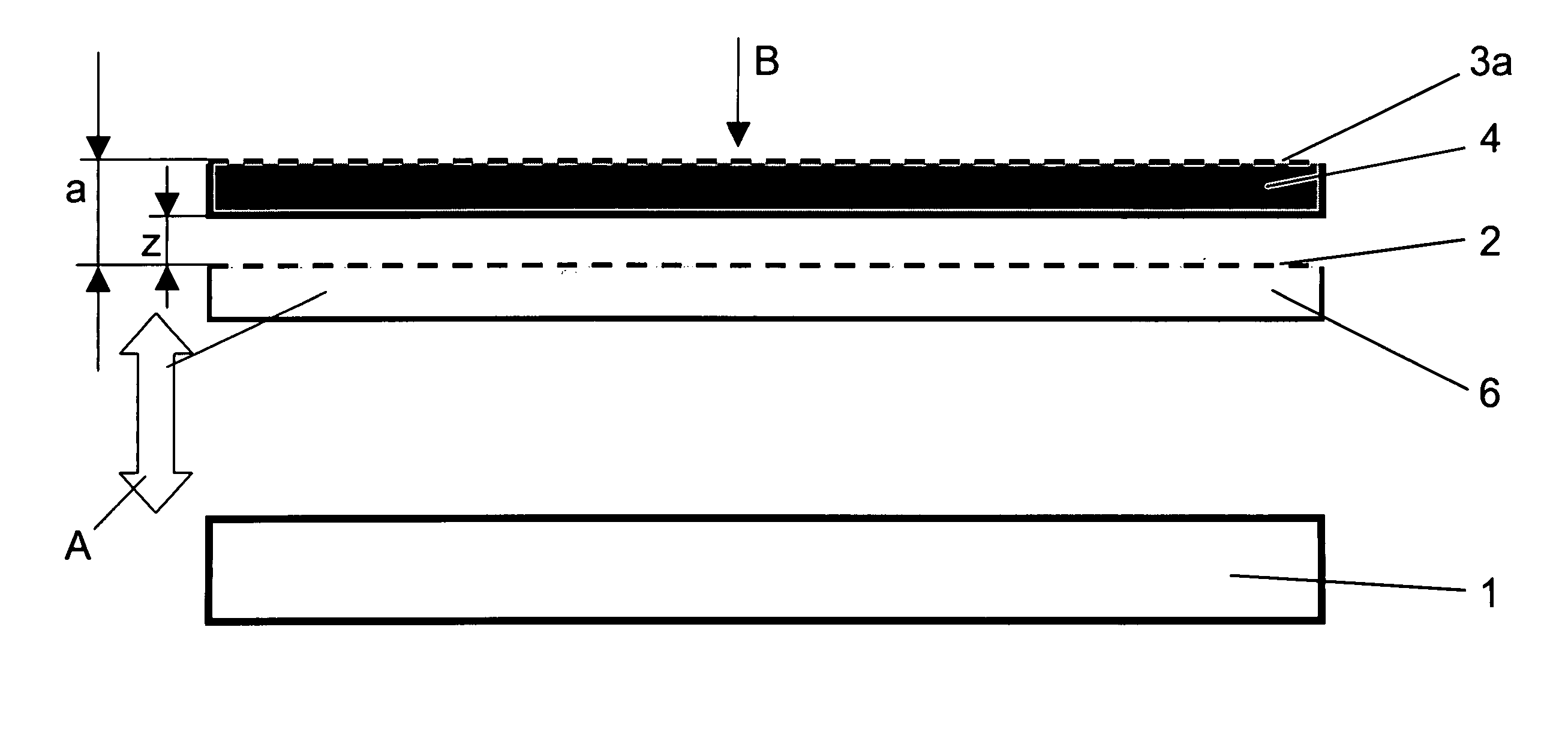
Figure 1 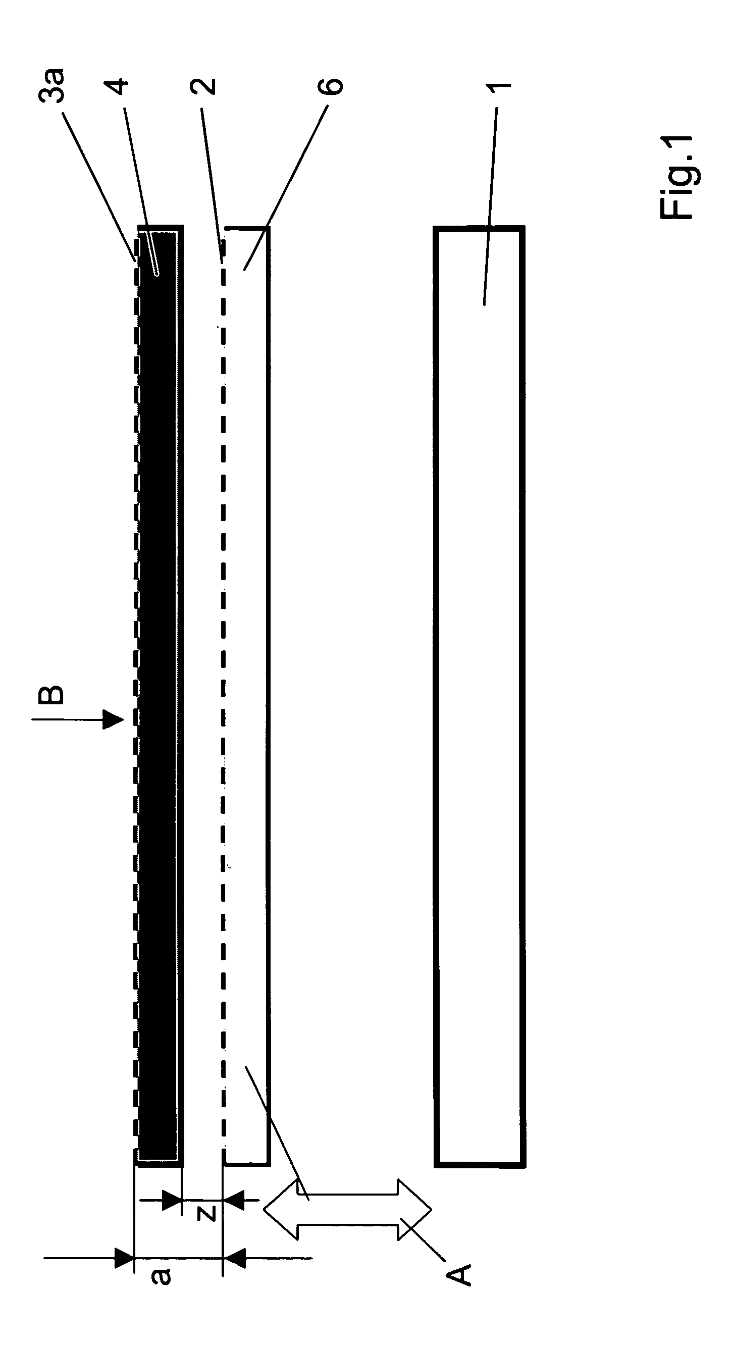
Figure 2 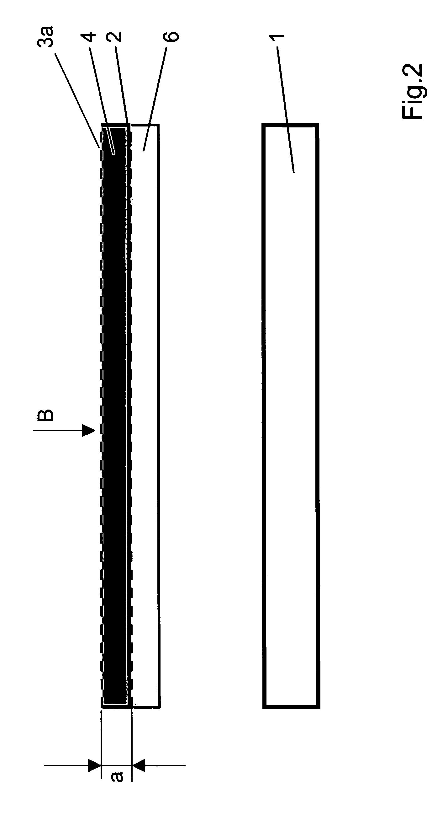
Figure 3
Abstract
Description
FIELD OF THE INVENTION
[0001] The invention relates to an arrangement for the display of images with selectable three-dimensionally visible or two-dimensional modes. It relates to autostereoscopic screens that optionally display a two-dimensional image of the usual quality.BACKGROUND OF THE INVENTION
[0002] In the course of research in the field of autostereoscopic display, a great number of methods and arrangements have been developed, which give impressions of space to one or several viewers. These arrangements, however, frequently allow but a limited presentation of common text or two-dimensional graphs, which is the case, e.g., with U.S. Pat. No. 5,457,574 and U.S. Pat. No. 5,606,455. For users it is of advantage, though, if they can switch between 3D display not requiring special eyeglasses and high-resolution, least-impaired 2D display on one and the same device.
[0003] Means used for the optical display of the perspective views of an object in autostereoscopic presentation include,...
Examples
first embodiment
[0081]FIG. 1 is a sketch illustrating the principle of a first embodiment version of the arrangement according to the invention. As shown in FIG. 1, the arrangement comprises an illuminating device 1 emitting light distributed over an area, a filter array 2 arranged before the illuminating device 1 ((in viewing direction B)) and intended to impart a structure to the light originating from the illuminating device 1, a diffusing layer 3a arranged before the filter array 2 and the image display device 4 ((in viewing direction B)), and, as an example, a transmissive image display device 4 arranged behind the diffusing layer 3a ((in viewing direction B)).
[0082]The diffusing layer 3a at the image display device is preferably a common antiglare matte finish as it is typical of LCD panels. The image display device 4 is rigidly connected with the illuminating device 1 through subassemblies not shown on the drawing. The filter array 2 is, for example, laminated onto a transparent substrate 6....
second embodiment
[0088]In a second embodiment version of the arrangement according to the invention, which is shown in FIG. 4, there are again provided (in the order of the viewing direction) a diffusing layer 3a, an image display device 4, a filter array 2 applied on a transparent substrate 6, and an illuminating device 1.
[0089]Unlike the first embodiment version, here the transparent substrate 6 and the filter array 2 are rigidly connected to the illuminating device 1, whereas the transparent substrate 6, the filter array 2 and the illuminating device 1 are arranged to be jointly movable for the purpose of varying the distance a, as again indicated by the arrow A. This corresponds to an embodiment according to version 2a. Here again, the movement can be implemented by very simple means.
[0090]By varying the distance a it is possible to set a 3D display mode (second position of the arrangement) as shown in FIG. 5, and a 2D display mode (first position of the arrangement) as shown in FIG. 6.
[0091]The...
third embodiment
[0092]Let a third embodiment version be explained with reference to FIG. 7. Here, the order in which the components are arranged corresponds to that in the embodiment versions already described, with the difference, however, that the image display device 4 and the diffusing layer 3a are arranged to be jointly movable for the purpose of varying the distance a, whereas a subassembly consisting of filter array 2, transparent substrate 6 and illuminating device 1 is relatively at rest or is attached in a fixed position relative to the chassis. This corresponds to the embodiment according to version 3a.
[0093]Analogously to the embodiment versions already described, the distance a shown in FIG. 8 illustrates a 3D viewing mode, and that shown in FIG. 9 illustrates a 2D viewing mode.