
Drive circuit and physical quantity measuring device
a technology of physical quantity and drive circuit, which is applied in the direction of generator/motor, mechanical vibration separation, instruments, etc., can solve problems such as unrealistic, and achieve the effect of stable measuremen
Patent Information
- Authority / Receiving Office
- US · United States
- Patent Type
- Patents(United States)
- Current Assignee / Owner
- Publication Date
- 2013-07-16
- Estimated Expiration
- Not applicable · inactive patent
Smart Images
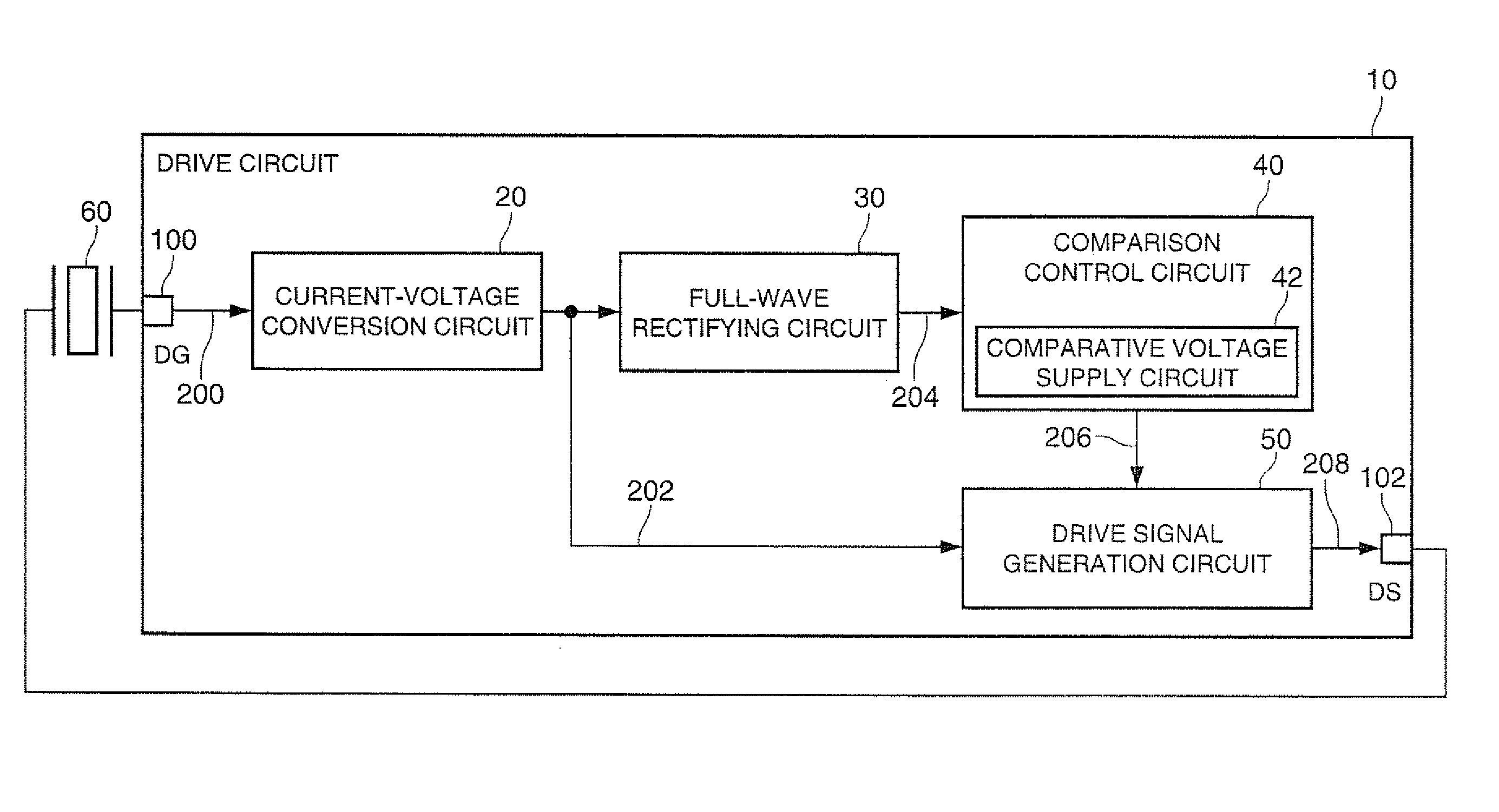
Figure 1 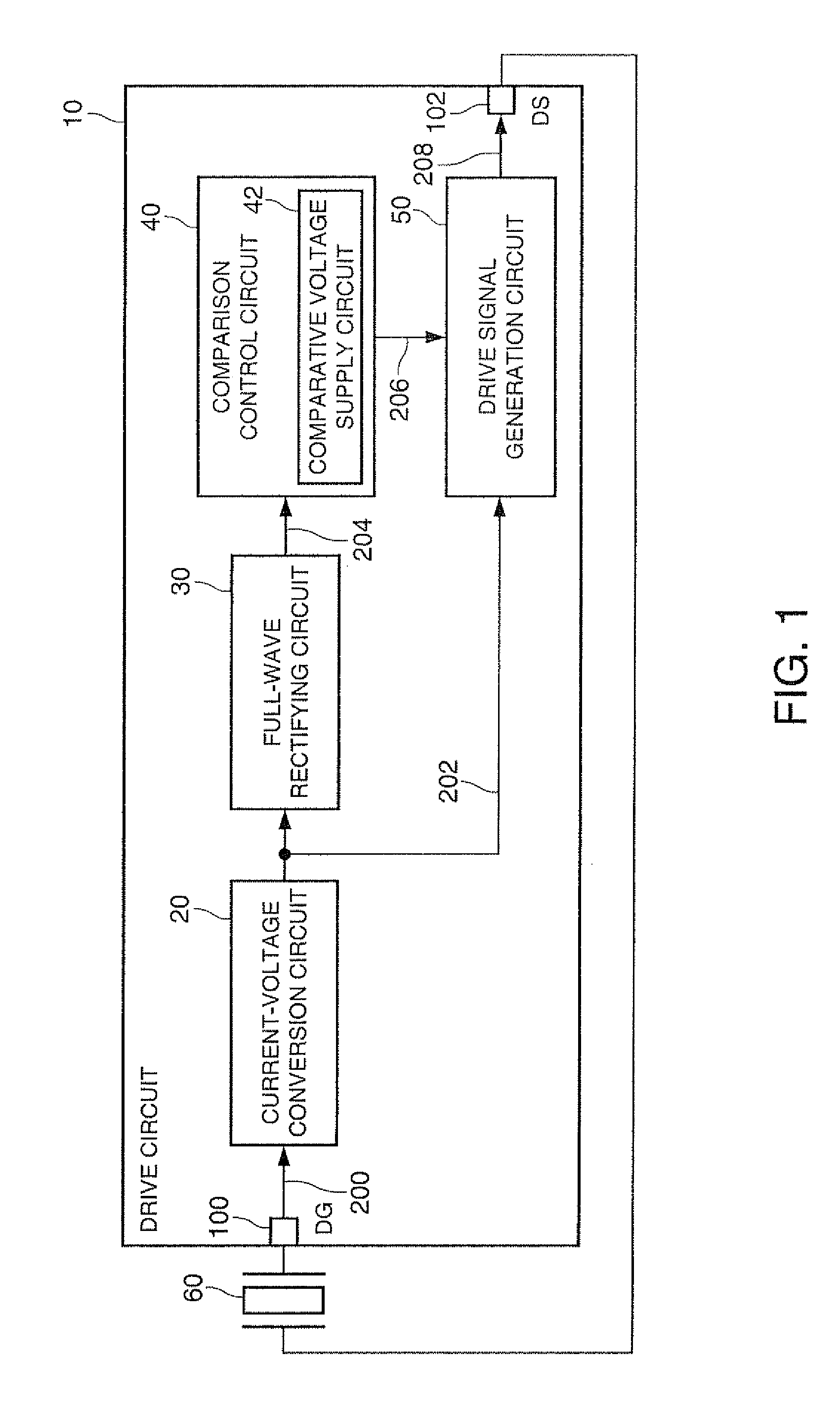
Figure 2 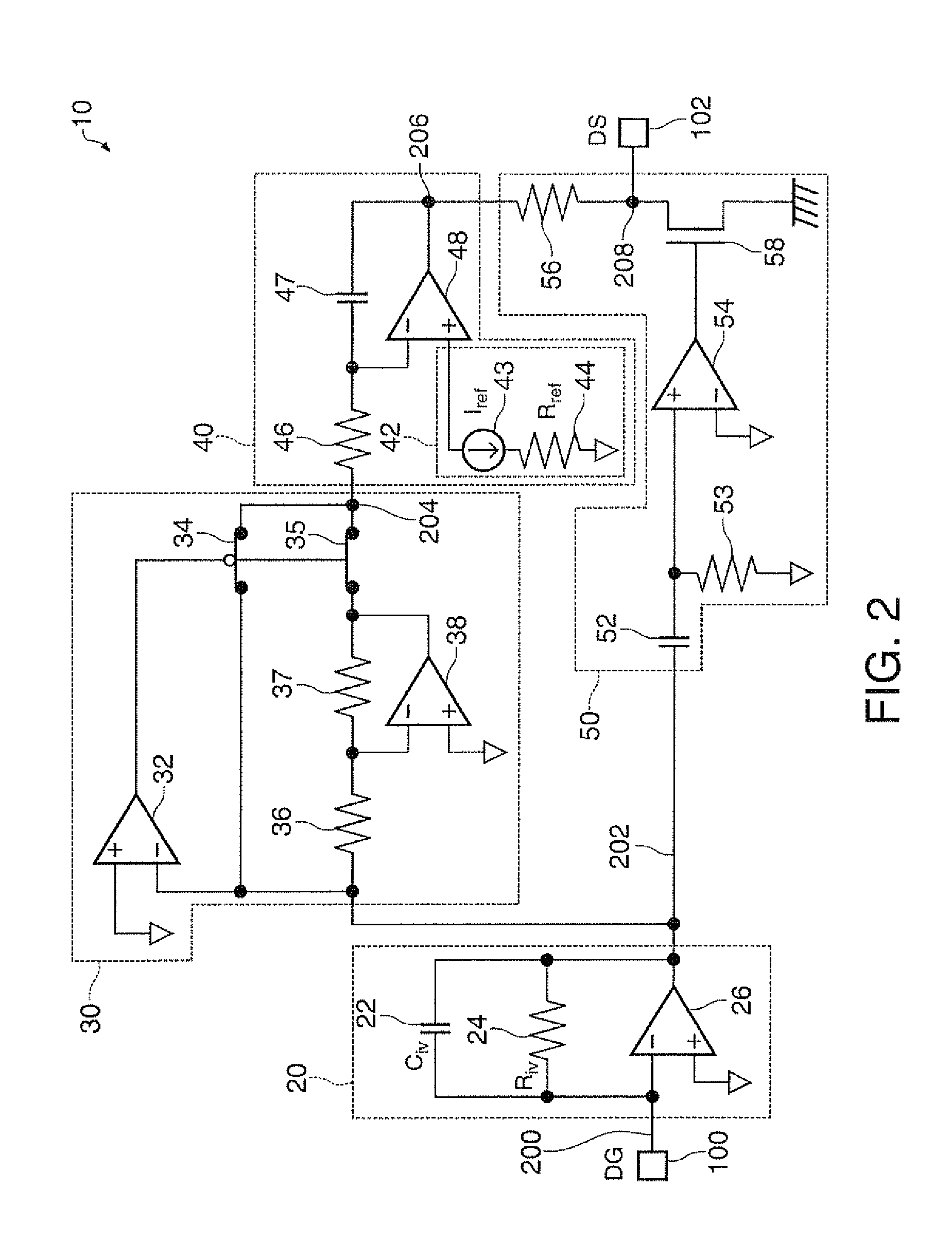
Figure 3
Abstract
Description
[0001] The entire disclosure of Japanese Patent Application No. 2010-196933, filed Sep. 2, 2010 is expressly incorporated by reference herein.BACKGROUND
[0002] 1. Technical Field
[0003] The present invention relates to a drive circuit, a physical quantity measuring device, and so on.
[0004] 2. Related Art
[0005] In general, a physical quantity measuring device using a vibrator outputs a measurement signal proportional to the excitation current of the vibrator. In order for stable measurement, there is required a drive circuit or the like for keeping the amplitude of the excitation current constant irrespective of the temperature variation in the measurement environment. In JP-A-2008-261844 (Document 1) there is disclosed an invention of using an element identical to the resistor element of the detection circuit in the drive circuit to thereby cancel out the temperature variation between the excitation current and the detection current, thus stabilizing the output of the measurement signal.[0...
Examples
first embodiment
1. First Embodiment
[0034]A first embodiment of the invention will be explained with reference to FIGS. 1, 2, 3A through 3C, and 4A through 4C. Further, FIGS. 6 and 7 are also referred to in the explanation of a comparative example.
1.1. Configuration of Drive Circuit of Present Embodiment
[0035]FIG. 1 is a block diagram of a drive circuit 10 according to the present embodiment. The drive circuit 10 includes a current-voltage conversion circuit 20, a full-wave rectifying circuit 30, a comparison control circuit 40, and a drive signal generation circuit 50.
[0036]The current-voltage conversion circuit 20 converts an excitation current 200 from a vibrator 60 into a voltage to thereby output an output voltage 202. The amplitude of the output voltage 202 is proportional to the amplitude of the excitation current 200.
[0037]The full-wave rectifying circuit 30 performs the full-wave rectification on the output voltage 202 from the current-voltage conversion circuit 20 to thereby obtain a rough...
application example
2. Application Example
[0095]An application example of the drive circuit according to the invention will be explained with reference to FIG. 5. The same constituents as those shown in FIGS. 1, 2, 3A through 3C, and 4A through 4C are provided with the same reference numerals, and the explanation therefor will be omitted.
2.1. Physical Quantity Measuring Device
[0096]FIG. 5 is a diagram showing an example of the physical quantity measuring device 1. The physical quantity measuring device 1 includes the drive circuit 10, a detection circuit 90, the vibrator 60, and a vibrator 70. The detection circuit 90 receives measurement signals 290, 292 as, for example, differential signals from a detection section provided to the vibrator 70. The measurement signals are proportional to the excitation current of the vibrator 60. Then, the detection circuit 90 receives necessary information from the drive circuit 10 as an internal signal 294, then performs a predetermined calculation, and then outputs...