
Method and device for controlling a reluctance electric machine
A control method and technology of reluctance motor, applied in the direction of controlling electromechanical transmission, controlling generator, controlling electromechanical brake, etc., can solve problems such as iron loss
Patent Information
- Authority / Receiving Office
- CN · China
- Patent Type
- Applications(China)
- Current Assignee / Owner
- Publication Date
- 2013-10-16
- Estimated Expiration
- Not applicable · inactive patent
Smart Images
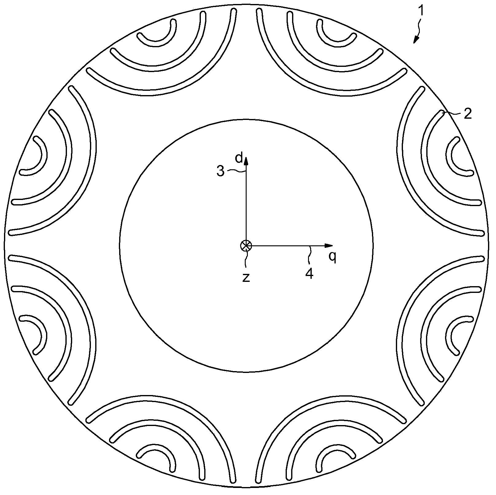
Figure 1 
Figure 2 
Figure 3
Abstract
Description
technical field
[0001] The subject of the invention is a method for controlling a motor known as a synchronous reluctance motor, and a motor suitable for being able to be controlled according to this method. Background technique
[0002] A synchronous reluctance machine comprises a series of stator windings defining the poles of the machine and a rotor which has been made of ferromagnetic material eg with a series of notches to make it easier to build up a magnetic field inside the rotor in certain specific directions.
[0003] Furthermore, the rotor can consist of a layered structure in order to limit the current flow within the rotor.
[0004] Such motors are often less expensive to produce than motors whose rotors include windings or permanent magnets. For a given current strength, the maximum torque that can be achieved depends inter alia on the control method.
[0005] Specifically, the mechanical power produced by an electric motor is proportional to the current inje...
Examples
Embodiment Construction
[0043] figure 1 A typical geometry of the rotor of a reluctance machine known as a "sinusoidal synchronous reluctance machine" is shown.
[0044] In this example, the rotor is shown in a plane perpendicular to the axisymmetric axis Z of the rotor.
[0045] The mass of the rotor 1 made of ferromagnetic material is indented by a notch 2 defined by a curved surface portion of a generatrix parallel to the axis z. In the example shown, the contour of the recess 2 is defined by a cylindrical portion of the shaft centered outside the outer circumference of the rotor 1 .
[0046]The end of the notch 2 is close to but not engaged with the outer circumference of the rotor 1 . The notches 2 delimit a smaller rectangular direction along which the orientation of the magnetic field induced inside the rotor 1 tends to be. Such a minimum reluctance axis is for example given by figure 1 Axis 3 or Axis D identification. exist figure 1 Also shown in is an axis q marked 4 perpendicular to b...