
Coordinated scheduling strategy for multi-element energy storage in distributed microgrid system for optical storage
A technology of multiple energy storage and coordinated scheduling, applied in the direction of AC network load balancing, reducing/preventing power oscillation, etc., can solve the problem of low energy storage power density and other issues
Patent Information
- Authority / Receiving Office
- CN · China
- Patent Type
- Patents(China)
- Current Assignee / Owner
- Publication Date
- 2016-08-24
- Estimated Expiration
- Not applicable · inactive patent
Smart Images
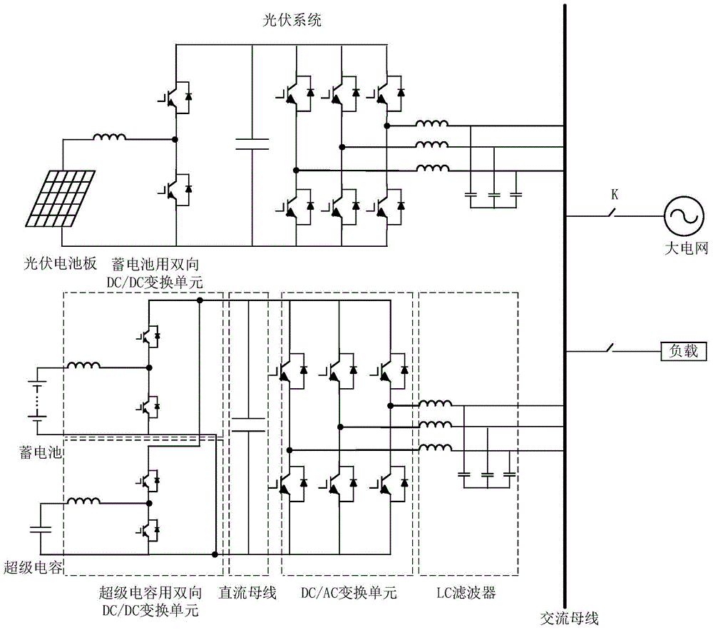
Figure 1 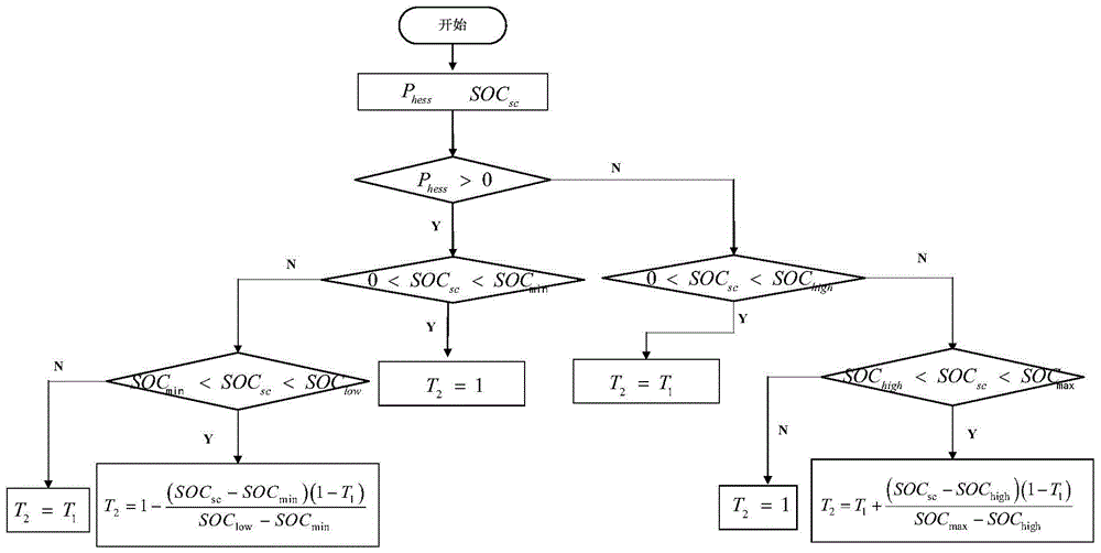
Figure 2 
Figure 3
Abstract
Description
Technical field
[0001] The invention relates to a multi-element energy storage coordinated scheduling method of a distributed optical storage micro-network system. Background technique
[0002] Distributed grid-connected photovoltaics are located in the vicinity of users, which can solve the power consumption of users nearby, reduce users’ dependence on grid power supply, and reduce grid line losses; and under appropriate conditions, with the energy storage system, combined with coordinated control strategies, it can be isolated from the grid. The net operates independently.
[0003] When distributed photovoltaic power generation is connected to the grid, the energy storage system can be used to effectively reduce the negative impact of grid-connected photovoltaic power generation output power fluctuations on the grid, and ensure that photovoltaic power generation can be reliably integrated into the conventional grid. In the island operation mode, the rapid response capability of ...
Examples
Embodiment Construction
[0068] The present invention will be further described below with reference to the drawings and specific embodiments.
[0069] figure 1 It is the topological structure of the two-stage converter for multi-element energy storage used in the method of the present invention. The two-stage converter for multiple energy storage includes a front-stage bidirectional DC / DC conversion unit and a rear-stage DC / AC conversion unit. The two-way DC / DC conversion unit for the battery and the two-way DC / DC conversion unit for the super capacitor share a DC bus. The battery and the super capacitor are connected to the two-way DC / DC conversion unit for the battery and the two-way DC / DC conversion unit for the super capacitor respectively. Connect the DC / AC conversion unit, connect the AC bus through the DC / AC conversion unit, and then connect the load and the large power grid through the LC filter.
[0070] figure 2 Is the second filter parameter T 2 Adjustment flow chart, when P hes > At 0, the...