
Method for determining a closed trajectory by means of a laser and a laser light sensor and apparatus for determining a closed trajectory curve
a laser light sensor and closed trajectory technology, applied in the direction of optical conversion of sensor output, measurement devices, instruments, etc., can solve the problems of insufficient accuracy, unusable vibration, and inability to use inclinometers, etc., to achieve the effect of precise accuracy in recording or determining the trajectory curv
Patent Information
- Authority / Receiving Office
- US · United States
- Patent Type
- Patents(United States)
- Current Assignee / Owner
- Publication Date
- 2017-02-21
Smart Images
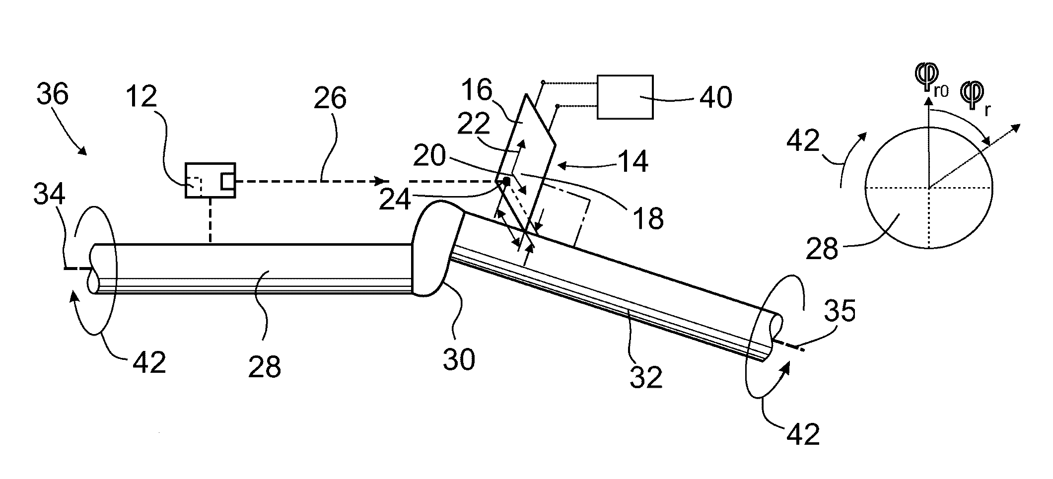
Figure 1 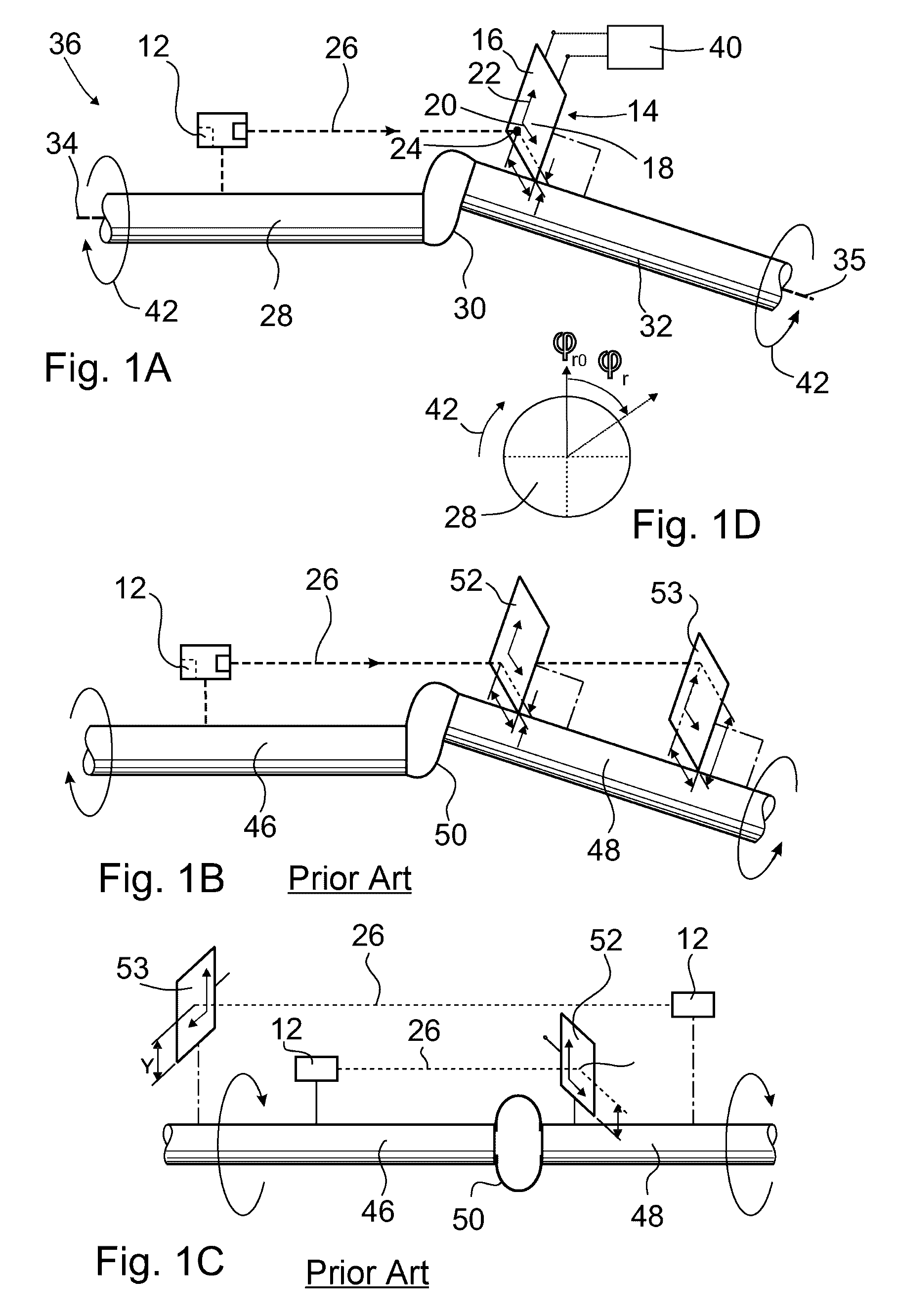
Figure 2 
Figure 3
Abstract
Description
BACKGROUND OF THE INVENTION
[0001] The present invention relates to a method for determining a closed trajectory curve by means of a laser and a laser light sensor having a flat field of view as well as an apparatus for determining a closed trajectory curve.
[0002] Methods and apparatuses of the kind mentioned in the introduction are used, in particular, for apparatuses and methods by means of which any existing misalignment of two shafts that are connected to each other by a coupling can be determined. Such misalignments, that is, deviations from the situation in which the axes of rotation or central axes of shafts that are connected to each other via the coupling are aligned, often lead to undesired vibrations during operation of the apparatus having the two shafts.
[0003] Methods and apparatuses for determining misalignment are known, for example, from DE 195 06 471 A1, DE 102 36 555 A1, DE 101 42 462 A1, DE 101 38 831 A1, and DE 39 11 307 A1.
[0004] Generally known from DE 199 49 834 A1...
Examples
Embodiment Construction
[0074]The apparatus 36 according to FIG. 1A for determining a closed trajectory curve comprises a laser 12, a laser light sensor 14 having a flat field of view 16, and an analysis unit 40.
[0075]The field of view 16 has a coordinate system 18 with an X coordinate axis 20 and a Y coordinate axis 22 that is at a right angle to the X coordinate axis 20.
[0076]The laser light sensor 14 is set up so as to record the X coordinate and Y coordinate of the position of the laser light spot 24 on the field of view 16 of the laser light beam 26 that can be generated by the laser 12 and impinges on the field of view 16.
[0077]The laser 12 can be linked to a first shaft 28 in a rotationally fixed manner, said shaft being connected to a second shaft 32 via a coupling 30, so that a rotation of the first shaft 28 can be transmitted to the second shaft 32 and vice versa.
[0078]The field of view 16 can be linked to the second shaft 32 in a rotationally fixed manner in such a way that the Y coordinate axis...