Synchronous Rectifier Faults: Shoot-Through, Reverse Conduction And Protections
SEP 22, 20259 MIN READ
Generate Your Research Report Instantly with AI Agent
Patsnap Eureka helps you evaluate technical feasibility & market potential.
Synchronous Rectification Technology Background and Objectives
Synchronous rectification technology emerged in the late 1980s as a significant advancement in power conversion systems, evolving from traditional diode rectification methods. This evolution was driven by increasing demands for higher efficiency and power density in electronic devices. The fundamental principle involves replacing passive diodes with actively controlled MOSFETs, which exhibit substantially lower conduction losses when properly driven. This transition has been particularly crucial in low-voltage, high-current applications where diode forward voltage drops represent a significant efficiency limitation.
The development trajectory of synchronous rectification has been closely tied to advancements in semiconductor technology, particularly the continuous improvement of MOSFET characteristics including reduced on-resistance, faster switching speeds, and enhanced thermal performance. Early implementations faced challenges with timing control and gate drive complexity, but modern integrated solutions have largely addressed these issues through sophisticated control algorithms and purpose-built driver ICs.
Industry adoption has accelerated dramatically over the past two decades, with synchronous rectification becoming standard in numerous applications including computer power supplies, telecommunications equipment, automotive systems, and renewable energy converters. This widespread implementation has been instrumental in meeting increasingly stringent energy efficiency regulations worldwide.
The primary technical objectives in synchronous rectification development focus on addressing three critical fault conditions: shoot-through events, reverse conduction scenarios, and implementing robust protection mechanisms. Shoot-through faults occur when both high-side and low-side MOSFETs conduct simultaneously, creating a destructive low-impedance path across the supply. Reverse conduction issues arise when MOSFETs unintentionally conduct in the reverse direction, potentially causing system instability and component damage.
Protection mechanisms represent a significant area of ongoing research, with objectives centered on developing faster fault detection methods, implementing more responsive protection circuits, and creating self-healing capabilities that can maintain system operation even after fault events. These protection strategies must balance response speed with immunity to false triggers that could unnecessarily interrupt power delivery.
Current research aims to push synchronous rectification technology toward higher switching frequencies, enabling smaller passive components and greater power density. Simultaneously, efforts are focused on improving light-load efficiency, enhancing thermal management, and developing more sophisticated control algorithms that can adapt to varying operating conditions. The integration of wide-bandgap semiconductors, particularly gallium nitride (GaN) and silicon carbide (SiC) devices, represents a promising frontier for extending the performance boundaries of synchronous rectification systems.
Market Demand Analysis for SR Applications
The synchronous rectifier (SR) market has witnessed substantial growth over the past decade, primarily driven by increasing demand for high-efficiency power conversion systems across multiple industries. The global SR market is currently valued at approximately 2.5 billion USD with a compound annual growth rate (CAGR) of 8.7% projected through 2028, indicating strong and sustained market demand.
Power supply efficiency requirements have become increasingly stringent across all electronic sectors, with regulations like 80 Plus Platinum and Titanium certifications for computer power supplies, and similar standards in telecommunications and industrial applications. These efficiency mandates have directly boosted SR adoption as a replacement for traditional diode rectification, which typically suffers from higher conduction losses.
Consumer electronics represents the largest application segment for SR technology, accounting for roughly 35% of the total market. The proliferation of smartphones, tablets, laptops, and other portable devices has created substantial demand for compact, efficient power conversion solutions where SR technology offers significant advantages in terms of thermal management and battery life extension.
The telecommunications and data center sectors collectively constitute approximately 28% of SR applications, driven by the exponential growth in cloud computing and network infrastructure. These facilities operate continuously and at scale, making even small efficiency improvements translate to substantial operational cost savings and reduced carbon footprints.
Automotive applications, particularly in electric vehicles (EVs) and hybrid electric vehicles (HEVs), represent the fastest-growing segment with a CAGR exceeding 12%. As vehicle electrification accelerates globally, the demand for high-efficiency power conversion components like synchronous rectifiers has surged, especially in onboard chargers and DC-DC converters.
Industrial applications account for approximately 22% of the SR market, with particular emphasis on motor drives, uninterruptible power supplies (UPS), and renewable energy systems. The industrial sector's focus on reliability and total cost of ownership has increased interest in SR solutions that offer improved fault tolerance and protection mechanisms.
Geographically, Asia-Pacific dominates the SR market with approximately 45% share, followed by North America and Europe. China's manufacturing ecosystem and growing domestic demand for consumer electronics and EVs have positioned it as the largest single country market for SR applications.
The market analysis indicates that fault protection features in SR systems have become a critical differentiator for manufacturers, with customers increasingly willing to pay premium prices for solutions that offer comprehensive protection against shoot-through, reverse conduction, and other failure modes that can compromise system reliability and safety.
Current Challenges in SR Fault Management
Despite significant advancements in synchronous rectifier (SR) technology, several critical challenges persist in fault management that impede optimal performance and reliability. The most pressing issue remains shoot-through current, where both high-side and low-side MOSFETs conduct simultaneously, creating a direct short circuit path. This phenomenon typically occurs during switching transitions due to improper gate timing control or parasitic turn-on effects, resulting in excessive power dissipation, thermal stress, and potential catastrophic device failure.
Reverse conduction management presents another significant challenge. When SR MOSFETs experience reverse voltage conditions without proper control mechanisms, body diode conduction or parasitic bipolar transistor activation can lead to substantial efficiency losses and reliability concerns. The body diode's relatively high forward voltage drop and slow reverse recovery characteristics contribute to increased power losses during these events.
False triggering of protection circuits represents a complex balancing act for designers. Overly sensitive protection mechanisms may cause unnecessary system shutdowns during normal transient events, while insufficiently responsive systems might fail to prevent damage during genuine fault conditions. This trade-off between nuisance tripping and adequate protection remains difficult to optimize across varying operating conditions.
Temperature-dependent fault behavior further complicates SR fault management. As operating temperatures increase, MOSFET characteristics change significantly, affecting threshold voltages, switching speeds, and leakage currents. Protection circuits must account for these temperature dependencies to maintain effective fault coverage across the entire operating temperature range.
Parasitic inductance in PCB layouts and component packaging introduces voltage spikes during switching transitions that can trigger false fault detection or even cause device failure. Minimizing these parasitic elements while maintaining practical manufacturing constraints continues to challenge designers, particularly as switching frequencies increase to improve power density.
Diagnostic capabilities present another ongoing challenge. Current SR controllers often provide limited visibility into fault conditions, making root cause analysis difficult. More sophisticated fault logging and communication features are needed to enable predictive maintenance and improve system reliability, but implementing these without increasing system complexity and cost remains problematic.
Finally, standardization gaps across the industry create interoperability issues between SR controllers from different manufacturers. The lack of unified approaches to fault detection, reporting, and protection protocols complicates system design and validation, particularly for applications requiring components from multiple vendors.
Existing Shoot-Through and Reverse Conduction Protection Methods
01 Shoot-through fault detection and prevention mechanisms
Shoot-through faults occur when both high-side and low-side switches in a synchronous rectifier conduct simultaneously, creating a direct short circuit. Detection circuits monitor current spikes or voltage anomalies to identify these events. Prevention mechanisms include implementing dead-time control, where a delay is inserted between switching transitions to ensure one switch is fully off before the other turns on. Advanced controllers can dynamically adjust this dead-time based on operating conditions to optimize efficiency while maintaining protection against shoot-through events.- Shoot-through fault detection and prevention mechanisms: Shoot-through faults occur when both high-side and low-side switches in a synchronous rectifier conduct simultaneously, creating a direct short circuit. Detection mechanisms monitor current spikes, voltage levels, or timing anomalies to identify potential shoot-through conditions. Prevention techniques include implementing dead-time control, gate drive optimization, and hardware protection circuits that can quickly disable switching operations when a fault is detected, thereby protecting power conversion systems from catastrophic failure.
- Reverse conduction protection in synchronous rectifiers: Reverse conduction occurs when current flows in the unintended direction through a synchronous rectifier, often during transient conditions or control failures. Protection circuits monitor the direction of current flow and voltage polarity across switching devices to detect reverse conduction events. When detected, these systems can implement various countermeasures including immediate switch turn-off, mode transitions, or activation of alternative current paths to prevent damage to semiconductor devices and maintain system stability.
- Timing control and dead-time management: Proper timing control between switching transitions is critical for preventing synchronous rectifier faults. Dead-time management ensures that high-side and low-side switches never conduct simultaneously by inserting a brief delay between switching operations. Adaptive dead-time controllers can dynamically adjust these delays based on operating conditions, temperature, and load requirements. Advanced implementations use predictive algorithms and real-time monitoring to optimize the balance between switching losses and fault prevention.
- Fault-tolerant synchronous rectifier architectures: Fault-tolerant designs incorporate redundancy, isolation mechanisms, and graceful degradation capabilities to maintain operation even when synchronous rectifier faults occur. These architectures may include parallel switching paths, backup operating modes, or segmented power stages that can be selectively disabled. Monitoring circuits continuously assess the health of switching components and can reconfigure the system topology or operating parameters to maintain critical functionality while minimizing the impact of component failures.
- Integrated protection and diagnostic systems: Modern synchronous rectifier controllers integrate comprehensive protection features with advanced diagnostic capabilities. These systems combine multiple fault detection methods including overcurrent sensing, thermal monitoring, and voltage anomaly detection to provide robust protection against both shoot-through and reverse conduction faults. Diagnostic functions can identify the root cause of failures, log fault events, and communicate status information to higher-level control systems, enabling predictive maintenance and improved system reliability.
02 Reverse conduction protection circuits
Reverse conduction in synchronous rectifiers occurs when current flows in the unintended direction through the MOSFET body diode or channel, potentially causing efficiency losses and device damage. Protection circuits detect reverse current conditions using current sensing techniques or voltage monitoring across the synchronous rectifier. When reverse conduction is detected, the system can either block the current path, adjust timing parameters, or safely shut down the converter. Some implementations use auxiliary switches or specialized gate drivers to prevent reverse conduction events.Expand Specific Solutions03 Timing control and gate drive optimization
Precise timing control of gate signals is critical for preventing synchronous rectifier faults. Advanced gate drive circuits implement adaptive timing algorithms that adjust turn-on and turn-off sequences based on load conditions, temperature, and other parameters. These systems monitor switching transitions and optimize gate drive parameters to minimize both shoot-through risk and body diode conduction losses. Some implementations include programmable delay circuits, slope control for gate signals, and feedback mechanisms that continuously adjust timing based on real-time operating conditions.Expand Specific Solutions04 Fault detection and protection control systems
Comprehensive fault detection systems monitor multiple parameters including current levels, voltage transients, and thermal conditions to identify synchronous rectifier faults. When abnormal conditions are detected, protection circuits implement appropriate responses such as soft shutdown, current limiting, or complete system isolation. Advanced implementations include diagnostic capabilities that can differentiate between fault types and record fault history for analysis. Some systems incorporate self-recovery mechanisms that attempt to resume normal operation after temporary fault conditions have cleared.Expand Specific Solutions05 Circuit topologies for fault-tolerant operation
Specialized circuit topologies are designed to inherently reduce susceptibility to synchronous rectifier faults. These include resonant and quasi-resonant converters that facilitate soft switching transitions, reducing stress during switching events. Some designs incorporate auxiliary circuits that provide alternative current paths during critical switching transitions. Other approaches use redundant components or parallel paths that can maintain operation even if one synchronous rectifier fails. Advanced topologies may implement current sharing techniques to distribute stress across multiple devices, reducing the likelihood of individual component failures.Expand Specific Solutions
Key Industry Players in SR Solutions
The synchronous rectifier fault protection market is in a growth phase, with increasing demand driven by power efficiency requirements in various electronic applications. The market size is expanding as power electronics become more prevalent in automotive, industrial, and consumer sectors. Technologically, the field is moderately mature but evolving rapidly with innovations in protection mechanisms against shoot-through and reverse conduction issues. Leading players include Texas Instruments, which offers comprehensive protection solutions, and STMicroelectronics with advanced fault detection technologies. NXP Semiconductors and ON Semiconductor (Semiconductor Components Industries) provide specialized synchronous rectifier controllers with integrated protection features. Delta Electronics and Murata focus on system-level implementations, while emerging players like Silergy and Mornsun are developing cost-effective solutions for growing Asian markets.
Texas Instruments Incorporated
Technical Solution: Texas Instruments has developed comprehensive solutions for synchronous rectifier fault management, particularly in their UCC series controllers. Their approach includes dedicated shoot-through protection circuits that implement adaptive dead-time control to prevent cross-conduction scenarios. TI's technology incorporates fast-response comparators that can detect reverse current conditions within nanoseconds and immediately disable the synchronous MOSFET gate drive[1]. Their solutions feature programmable blanking times to avoid false triggering during switching transitions while maintaining protection integrity. TI has also implemented cycle-by-cycle current monitoring with adjustable thresholds that can respond to overcurrent events without shutting down the entire power system unnecessarily. Their integrated solutions often combine multiple protection features including thermal shutdown, undervoltage lockout, and overvoltage protection alongside the synchronous rectifier fault management[2].
Strengths: Highly integrated solutions that combine multiple protection features in single ICs, reducing component count and system complexity. Advanced adaptive dead-time control algorithms that optimize efficiency while maintaining robust protection. Weaknesses: Some solutions may require more complex configuration and tuning compared to simpler alternatives, potentially increasing design time. Higher-end protection features often come with price premium compared to basic synchronous rectifier controllers.
Stmicroelectronics Srl
Technical Solution: STMicroelectronics has developed sophisticated synchronous rectifier controllers with comprehensive fault protection mechanisms. Their technology implements dynamic dead-time adjustment that continuously monitors switching conditions to prevent shoot-through scenarios while optimizing efficiency. ST's solutions feature ultra-fast fault detection circuits capable of responding within 50-100ns to reverse conduction events[3]. Their synchronous rectifier ICs incorporate proprietary sensing technology that can accurately detect drain-to-source voltage polarity changes with minimal external components. ST has also implemented multi-level protection schemes that provide graduated responses based on fault severity - from cycle-by-cycle management of minor events to complete shutdown for persistent faults. Their controllers typically include built-in protection against undervoltage, overvoltage, and thermal conditions alongside the core synchronous rectifier protections[4]. ST's solutions often feature programmable thresholds and blanking times to allow designers to optimize the balance between protection sensitivity and operational robustness.
Strengths: Extremely fast response times to fault conditions, minimizing potential damage from shoot-through events. Highly configurable protection parameters allowing optimization for specific application requirements. Weaknesses: Some solutions require more complex PCB layouts to maintain signal integrity for the high-speed protection circuits. Higher implementation complexity compared to basic synchronous rectifier solutions.
Critical Patents and Innovations in SR Fault Protection
System for synchronous rectifier voltage regulator shoot-through detection
PatentActiveUS10185381B2
Innovation
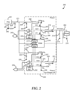
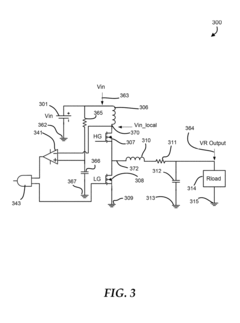
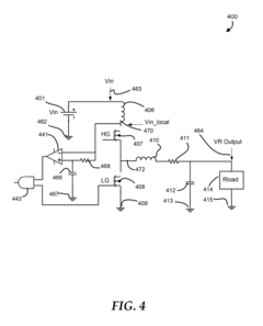
- A method that involves detecting the assertion of a low-side gate driver signal, obtaining a reference voltage, comparing it to the local high-side positive supply voltage, and providing a warning of cross-conduction detection before failure occurs, using a circuit that includes comparators and logic gates to validate the voltage drop as a shoot-through event, thus avoiding false indications.
System and method for synchronous rectification with enhanced detection of small currents
PatentActiveUS20160336871A1
Innovation
- The synchronous rectifier circuit operates in multiple states, including an enhanced detection mode, where low-resistance and high-resistance switches are used in parallel to improve detection accuracy by transitioning between states based on voltage thresholds, allowing for precise control of switches during polarity reversals.
Reliability Testing Standards for SR Circuits
Reliability testing standards for synchronous rectifier (SR) circuits have evolved significantly to address the unique failure modes these components face. The International Electrotechnical Commission (IEC) has established IEC 60747-8 specifically for power semiconductor devices, which includes testing protocols for synchronous rectifiers. These standards define rigorous methodologies for evaluating SR circuit reliability under various stress conditions, with particular emphasis on shoot-through and reverse conduction vulnerabilities.
JEDEC standards, particularly JESD22-A108 for temperature cycling and JESD22-A104 for thermal shock, provide critical frameworks for assessing SR circuit durability. These standards require SR circuits to withstand between 500-1000 temperature cycles from -40°C to 125°C without performance degradation. Additionally, AEC-Q101 qualification requirements have become increasingly important for SR circuits in automotive applications, where reliability expectations are exceptionally high.
Specific to shoot-through fault testing, standards mandate evaluation under various gate drive conditions with dV/dt rates ranging from 5V/ns to 50V/ns. These tests verify the SR's immunity to parasitic turn-on events that could lead to catastrophic failures. For reverse conduction scenarios, testing protocols require verification of body diode behavior under various temperature conditions, with particular attention to recovery characteristics and voltage spikes.
Surge immunity testing follows IEC 61000-4-5 guidelines, requiring SR circuits to withstand voltage surges of 1-2kV without permanent damage. Accelerated life testing standards dictate that SR circuits must operate reliably for 1000 hours under elevated temperature and voltage conditions (typically 125°C and 120% of rated voltage) with failure rates below defined PPM thresholds.
Environmental testing standards have also been adapted specifically for SR applications, with humidity bias tests (85°C/85% RH for 1000 hours) becoming standard practice. These tests evaluate the susceptibility of SR circuits to moisture-induced failures, particularly in gate drive circuitry where insulation degradation can lead to shoot-through events.
Recent updates to reliability standards have incorporated specific provisions for wide bandgap semiconductor-based SR circuits, recognizing their unique characteristics and failure modes. These standards include specialized dV/dt immunity tests and gate oxide reliability evaluations that reflect the higher switching speeds and voltage ratings of GaN and SiC devices used in modern SR implementations.
Thermal Management Considerations in SR Design
Thermal management represents a critical aspect of synchronous rectifier (SR) design, particularly when addressing fault conditions such as shoot-through and reverse conduction. The thermal behavior of SR MOSFETs during normal operation and fault scenarios directly impacts reliability, efficiency, and overall system performance.
Power dissipation in SR MOSFETs occurs through multiple mechanisms, with conduction losses and switching losses being predominant. During shoot-through events, when both high-side and low-side MOSFETs conduct simultaneously, extreme current spikes generate substantial heat that can rapidly exceed thermal limits. This necessitates careful thermal design considerations to prevent catastrophic device failure.
Junction temperature management emerges as the primary thermal design parameter, with most SR MOSFETs rated for maximum junction temperatures between 150°C and 175°C. Effective thermal resistance paths must be established from junction to ambient, typically involving multiple interfaces: junction-to-case, case-to-heatsink, and heatsink-to-ambient. The thermal resistance network determines how efficiently heat dissipates away from critical components.
Layout considerations significantly influence thermal performance in SR designs. Copper pour areas, thermal vias, and component placement must be optimized to facilitate heat spreading. High-current paths require wider traces and strategic via placement to minimize resistance and associated heating. Modern designs increasingly employ thermal simulation tools during the development phase to identify potential hotspots before physical prototyping.
Dynamic thermal management techniques have evolved to address transient fault conditions. These include adaptive gate driving schemes that modify switching parameters based on temperature feedback, and intelligent protection circuits that can detect temperature excursions and implement appropriate responses before thermal runaway occurs. Temperature sensors strategically placed near SR MOSFETs provide real-time monitoring capabilities.
Cooling solutions vary based on power density requirements, with passive approaches utilizing heatsinks and enhanced PCB designs for lower-power applications, while active cooling through fans or liquid cooling systems becomes necessary for high-power density designs. The selection of thermal interface materials between components and heatsinks critically affects overall thermal performance.
Thermal cycling due to intermittent fault conditions presents reliability challenges beyond steady-state thermal management. Repeated expansion and contraction from temperature fluctuations can lead to solder fatigue, bond wire stress, and eventual failure. Accelerated life testing that incorporates thermal cycling has become standard practice to validate SR designs for long-term reliability under fault conditions.
Unlock deeper insights with Patsnap Eureka Quick Research — get a full tech report to explore trends and direct your research. Try now!
Generate Your Research Report Instantly with AI Agent
Supercharge your innovation with Patsnap Eureka AI Agent Platform!
