Erecting method and structure of piece-by-piece assembling formworks at position of interlayer outer wall construction joint

A technology of construction joints and external formwork, which is applied in the direction of formwork/formwork/work frames, walls, building components, etc., can solve problems that affect structural safety and appearance quality, grout leakage and misalignment, and cross-sectional size effects, etc., to achieve It is convenient to check and check the straightness and cross-sectional size, avoiding slurry leakage and wrong platform, and the effect of tight joints between the upper and lower layers

Active Publication Date: 2013-09-25
CHINA CONSTR EIGHT ENG DIV CORP LTD
View PDF4 Cites 5 Cited by
  • Summary
  • Abstract
  • Description
  • Claims
  • Application Information

AI Technical Summary

Problems solved by technology

However, as the requirements for project quality become higher and higher, its shortcomings such as joints, grout leakage, misalignment, and deformation are becoming more and more obvious, which not only affects the structural safety and appearance quality, but also increases the post-processing costs. Affect the development of various tasks
Especially the detailed treatment of the construction joints of the outer wall between floors, the grout leakage and the wrong platform caused by the lax joints have long been a problem that has plagued people
Once there is a phenomenon of slurry leakage and wrong platform, it is very troublesome to deal with, laborious and costly, and it will affect the image if it is not dealt with in time
[0003] Therefore, various units actively take different measures for pre-control, such as: someone puts a long wooden square at the bottom of the outer wall formwork, this method can reduce the leakage of grout, but the phenomenon of wrong platform often occurs; someone adds sponge strips to the outer wall, this method is beneficial The straightness of the outer edge of the finished concrete wall is relatively high, otherwise it cannot be squeezed tightly, and there will still be phenomena such as grout leakage and misalignment; some people add a wooden wedge at each keel at the bottom of the wall formwork to make the formwork close to the wall In this method, the loss of wood is large, and it will affect the cross-sectional size; there are many similar methods, but they are not guaranteed to be in close contact with the completed concrete wall, so as to fundamentally solve the problem

Method used


Image

  • Erecting method and structure of piece-by-piece assembling formworks at position of interlayer outer wall construction joint
  • Erecting method and structure of piece-by-piece assembling formworks at position of interlayer outer wall construction joint
  • Erecting method and structure of piece-by-piece assembling formworks at position of interlayer outer wall construction joint

Examples


Embodiment Construction

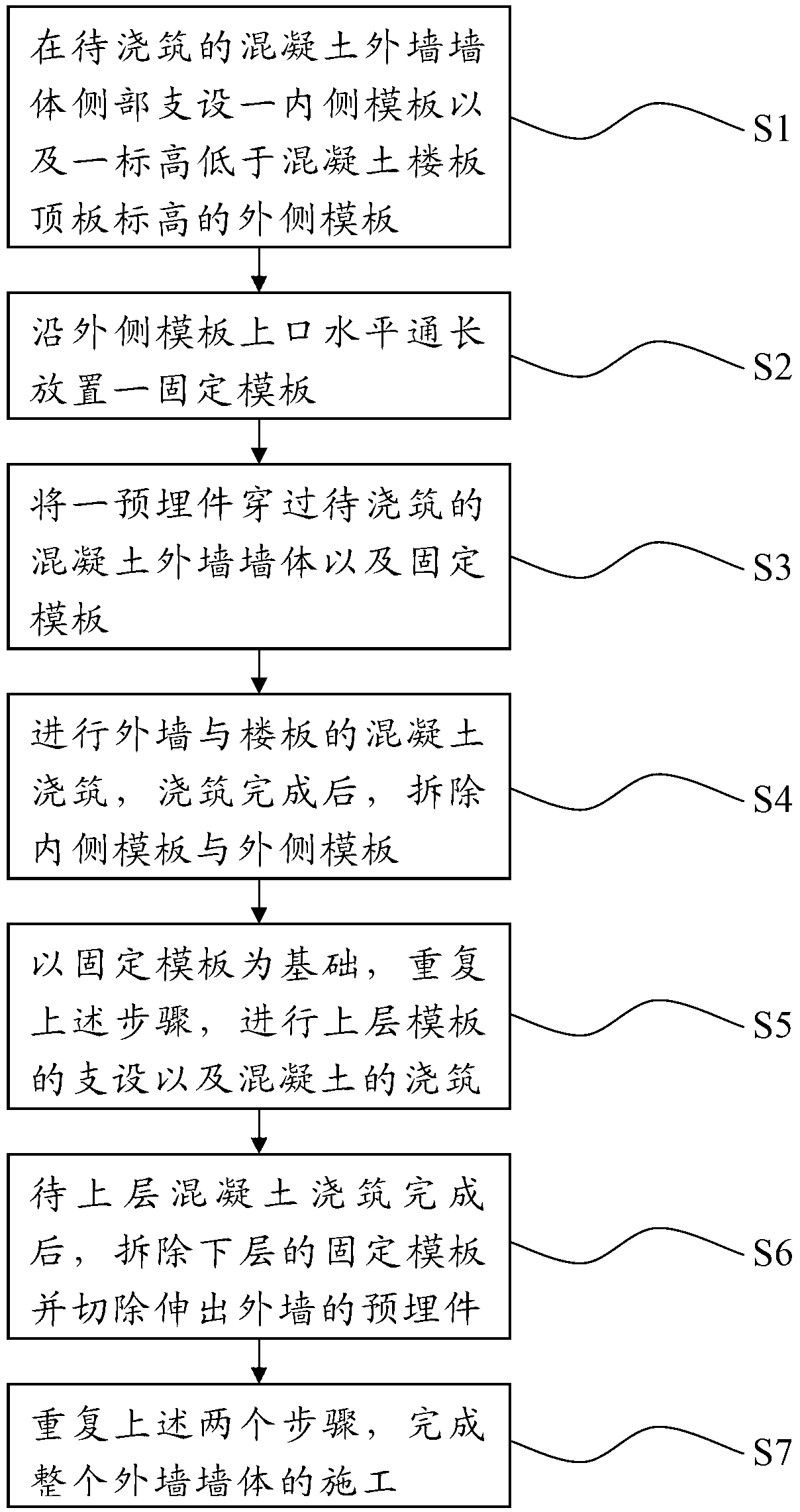
[0029] In order to make the object, technical solution and advantages of the present invention clearer, the present invention will be further described in detail below in conjunction with the accompanying drawings and embodiments. It should be understood that the specific embodiments described here are only used to explain the present invention, not to limit the present invention.

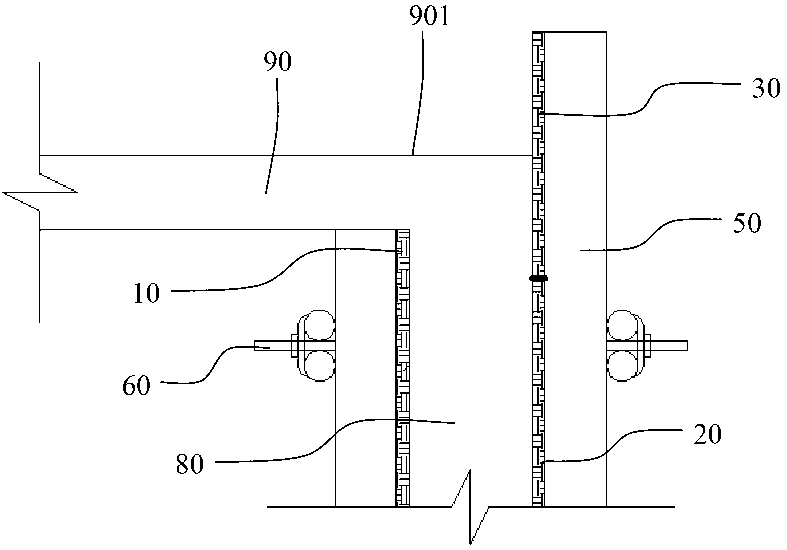
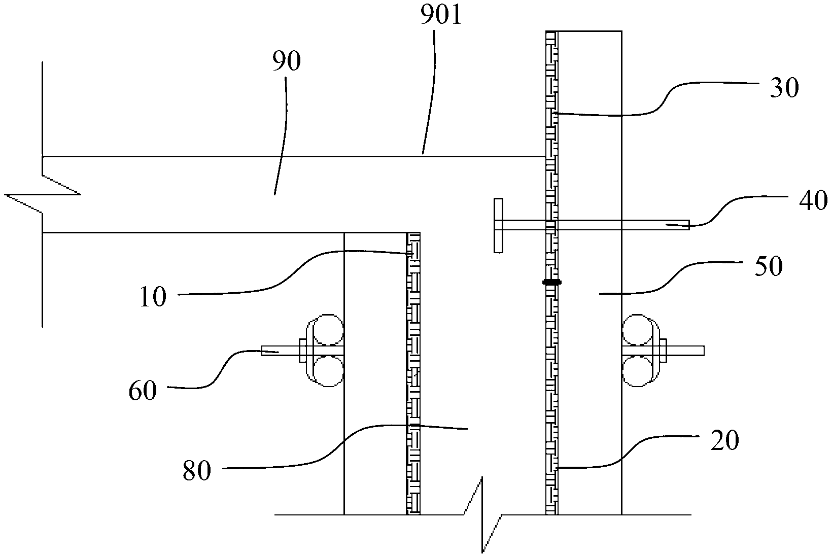
[0030] Cooperate with reference figure 2 As shown, the scattered formwork structure at the construction joint of the interlayer outer wall of the present invention includes an inner formwork 10 and an outer formwork 20 supported on the side of the concrete outer wall body 80 to be poured, and the elevation of the outer formwork 20 is as follows: A preset value is lower than the elevation of the top plate 901 of the concrete floor 90, and a fixed formwork 30 with a width greater than the preset value is placed along the upper horizontal length of the outer formwork 20, and the fixed formwork 30 pas...


PUM


Abstract

The invention discloses an erecting method of piece-by-piece assembling formworks at the position of an interlayer outer wall construction joint. The method comprises the following steps of (1) erecting an inner side formwork and an outer side formwork with elevation lower than that of a concrete floor slab top plate at the side portion of a concrete outer wall body to be poured, (2) placing a fixed formwork along the horizontal pass length of an upper port of the outer side formwork, (3) enabling an embedded part to penetrate the concrete outer wall body to be poured and the fixed formwork, (4) performing concrete pouring of an outer wall and a floor slab and dismounting the inner side formwork and the outer side formwork after the pouring is finished, (5) using the fixed formwork as a basis, repeating the steps to perform erection of the upper-layer formworks and the concrete pouring, (6) dismounting the lower-layer fixed formwork and cutting off the portion of the embedded part extending out of the outer wall after the upper-layer concrete pouring is finished, (7) repeating the steps (5) and (6) to finish construction of the whole outer wall body. By means of the erecting method of the piece-by-piece assembling formworks at the position of the interlayer outer wall construction joint, joint-free combination of wall bodies is ensured, and grout leakage and slab staggering are avoided.

Description

technical field [0001] The present invention relates to a formwork support method and structure, in particular to a formwork support method and structure at construction joints of outer walls between floors. Background technique [0002] Concrete structure is mainly composed of steel bars, formwork, and concrete. Among them, formwork engineering is the most complicated and labor-intensive sub-item, and it has become a key factor affecting project quality and project progress. Although the stereotyped formwork, all-steel large formwork, etc. are now being vigorously promoted, and various other new formworks are also emerging, the bulk formwork still occupies most of the market due to its low cost, convenient transportation, and flexible assembly. However, as the requirements for project quality become higher and higher, its shortcomings such as joints, grout leakage, misalignment, and deformation are becoming more and more obvious, which not only affects the structural safety...

Claims


Application Information

Patent Timeline
Patent Type & Authority Applications(China)
IPC IPC(8): E04G11/08E04B2/84
Inventor 周英杰任富海陈俊杰张书强曹海良
Owner CHINA CONSTR EIGHT ENG DIV CORP LTD
Why Eureka
Try Eureka