
Multipurpose disc-type turning cutter head for crankshafts
A multi-purpose, cutter head technology, used in crankshafts, shafts, shafts and bearings, etc., can solve problems such as insufficient rigidity, easy vibration of the knife, influence, etc., to achieve the effect of simple structure, solving interference, and meeting rigidity requirements
Patent Information
- Authority / Receiving Office
- CN · China
- Patent Type
- Applications(China)
- Current Assignee / Owner
- Publication Date
- 2014-10-15
- Estimated Expiration
- Not applicable · inactive patent
Smart Images
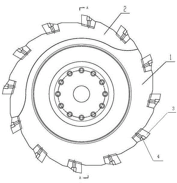
Figure 1 
Figure 2
Abstract
Description
technical field
[0001] The invention relates to a cutterhead for axle parts, in particular to a multipurpose disc turning cutterhead for crankshafts. Background technique
[0002] We know that due to the particularity of the crankshaft structure, in the crankshaft turning process, a multi-tool turret is used. Due to the limited gear width of the main shaft journal or connecting rod journal, the tool bar installed on the turret can only be designed to be long. And narrow structure, no back support device in the process of processing, insufficient rigidity, easy to vibrate the tool, affecting the improvement of processing quality and processing efficiency. The pull-type disc cutterhead is used. The design width is too wide to meet the gravity cutting during rough machining. Because the cutterhead is too wide and there is machining interference, it cannot be used for finishing machining. The cutterhead is too narrow to meet finishing machining. Due to insufficient rigidity, Gr...
Examples
Embodiment Construction
[0013] from figure 1 , figure 2 It can be seen from the figure that a crankshaft multi-purpose disc-type turning cutter head is provided with a cutter head main body, and the cutter head main body is installed on a machine tool interface. A part of the main body of the cutterhead is a wide cutterhead area 1, and a part is a narrow cutterhead area 2. A plurality of knife holders are evenly arranged on the outer sides of the wide cutterhead area and the narrow cutterhead area, and the knife holders are passed through screws 4 Turning tool 3 is installed.
[0014] A wide turning tool with the same width is installed on the circumferential outer side of the wide cutter head area 1 , and a narrow turning tool with the same width is installed on the circumferential outer side of the narrow cutter head area 2 .
[0015] The wide cutter head area on the cutter head main body is larger than the narrow cutter head area.
[0016] from figure 2 It can also be seen from the figure th...