Waveguide laser

a laser and waveguide technology, applied in the field of waveguide lasers, can solve the problems of inability to cost-effectively fabricate a typical waveguide structure, inability to meet the requirements of laser transverse mode characteristics, and difficulty in achieving sufficient accuracy of waveguides, etc., to achieve the effect of increasing laser power and/or efficiency

Inactive Publication Date: 2006-05-23
VIDEOJET TECH INC
View PDF46 Cites 10 Cited by
  • Summary
  • Abstract
  • Description
  • Claims
  • Application Information

AI Technical Summary

Benefits of technology

[0016]Exemplary embodiments of the present invention provide for increased laser power and / or efficiency by optimizing electrode spacing.
[0017]An exemplary embodiment of the present invention provides a waveguide laser having a waveguide located in a laser resonator cavity defined by a first and second reflecting means at opposite ends of the waveguide enclosed in a sealed vessel. The waveguide structure is made up of multiple pieces that when joined together form the waveguide walls. The waveguide walls can be made up of individual pieces that allow the walls to be more accurately aligned. The individual pieces can be abutted one to another, or can be separated by a gap with little degradation in the laser power or mode.

Problems solved by technology

Waveguide lasers suffer from the disadvantage that, for the lengths needed, the waveguides are difficult to fabricate with sufficient accuracy at a reasonable cost to obtain acceptable laser performance.
It is very difficult to cost-effectively fabricate a typical waveguide structure that is roughly 30 to 40 cm long with a 1.5 to 3.0 mm bore.
Bore cross-section inaccuracy leads to unacceptable laser transverse mode characteristics and reduced power output.
Casting or extruding tolerances are high, requiring expensive machining (grinding) after the piece is formed to acquire the desired accuracy.
Additionally, a waveguide laser balances it's loss in inherent internal RF circuit, and heat removal efficiency.
With Al2O3, thermal efficiency requirements dictate the use of a large ceramic area, which creates either a higher loss RF circuit, and / or high manufacturing costs.
Ideally materials with good thermal properties such as BeO and AlN are desirable ceramics to use, but are prohibitively expensive with related art waveguide designs.
Additionally, the resonator cavities of waveguide lasers suffer energy losses from misalignment of the containment mirrors and low reflectivity properties of the containment.
For example, the use of curved containment mirrors results in variable beam radius throughout the resonator cavity, thus the waveguide channels of related art fail to allow the optimization of the waveguide with respect to variable beam radius in the resonator channel.
Various spacing between electrodes results in varying power levels and the related art fails to fully optimize the electrode spacing and optics, and instead conventional methods focus on ease of manufacture.
Additional problems exist in conventional gaseous lasers, for example, laser startup.
Traditional CO2 lasers are pressurized at 70–80 torr and have difficultly starting without some manipulation of the RF system.

Method used


Image

  • Waveguide laser
  • Waveguide laser
  • Waveguide laser

Examples


Embodiment Construction

[0030]The following description of exemplary embodiment(s) is merely illustrative in nature and is in no way intended to limit the invention, its application, or uses.

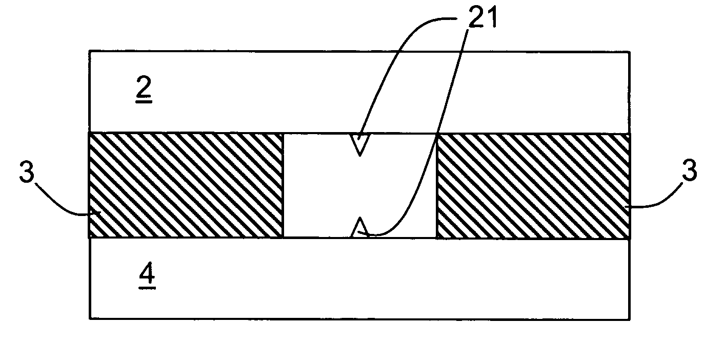
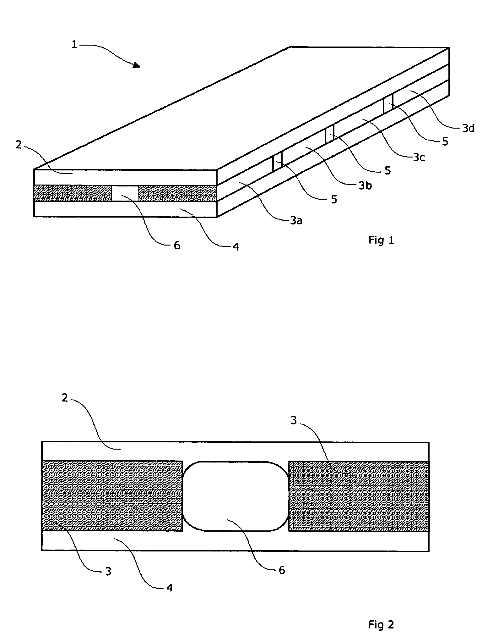
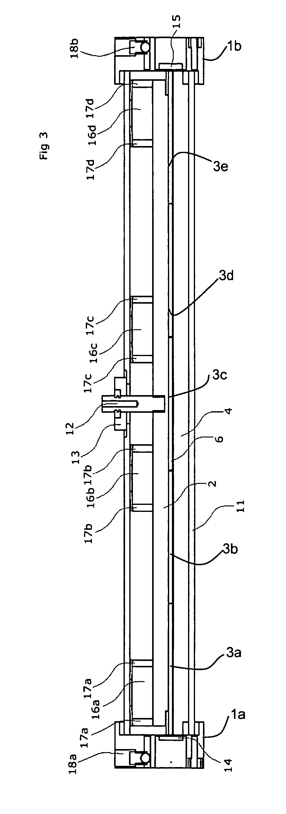
[0031]FIG. 1 shows a slab waveguide laser 1 according to an exemplary embodiment of the present invention, comprising a top or upper electrode 2 and a bottom or lower electrode 4. The upper and lower electrodes, 2 and 4 respectively, can have variable shape (e.g., planar, variable thickness, curved . . . ). Sidewalls 3a, 3b, 3c, and 3d are sandwiched between the upper electrode 2 and the lower electrode 4 and can be separated by small gaps 5. The width and thickness of the sidewalls are shown shaded. The length of the sidewalls are not shaded.

[0032]The sidewalls 3a, 3b, 3c, and 3d and the upper and lower electrodes 2 and 4 respectively can form a waveguide 6. There can be gaps 5 between the sidewalls 3a, 3b, 3c, and 3d or no gap. In exemplary embodiments of the present invention there can be any number of gaps. In addi...


PUM


Abstract

A laser waveguide, where the laser waveguide can be formed by electrodes and at least one sidewall in a manner allowing a more compact structure than previously provided. Protrusions in the electrodes allow easier laser starts, and sectional sidewall(s) allow easier fabrication of sidewall(s), decreasing manufacturing costs.

Description

CROSS-REFERENCE TO RELATED APPLICATIONS[0001]This application claims the benefit of U.S. provisional patent application No. 60 / 467,542 filed on 2 May 2003.FIELD OF THE INVENTION[0002]The invention relates in general to waveguide lasers and particularly but not exclusively to RF excited waveguide lasers.BACKGROUND OF THE INVENTION[0003]A waveguide laser typically consists of two mirrors, concave or flat, defining an optical resonator cavity coupled together with a waveguide defining an optical path between the mirrors.[0004]The waveguide is typically a channel ground into a ceramic block (e.g. aluminum oxide, Al2O3) with a lower electrode of aluminum or copper added to complete a cross-section of the waveguide. Alternatively, the waveguide can be ultrasonically drilled down through a piece of ceramic such as aluminum oxide (Al2O3) to create a continuous closed bore length with upper and lower electrodes parallel to the bore length. Typically, the positive arm of the oscillating elect...

Claims


Application Information

Patent Timeline
Patent Type & Authority Patents(United States)
IPC IPC(8): H01S3/22H01S3/03H01S3/097G05B19/18H01SH01S3/038H01S3/063H01S3/0975H01S3/223
CPCH01S3/0315H01S3/0385H01S3/0975H01S3/22H01S3/0632H01S3/063
Inventor MONTY, NATHAN PAUL
Owner VIDEOJET TECH INC
Why Eureka
Try Eureka