
No contact energy-saving starter
A starter and non-contact technology, applied in the direction of motor generator/starter, single-phase induction motor starter, etc., can solve the problems of narrowing the scope of application, limitation of versatility, electromagnetic interference, etc., and achieve reliability Improve and reduce heating energy consumption, good starting effect
Patent Information
- Authority / Receiving Office
- CN · China
- Current Assignee / Owner
- Publication Date
- 2007-10-17
- Estimated Expiration
- Not applicable · inactive patent
Smart Images
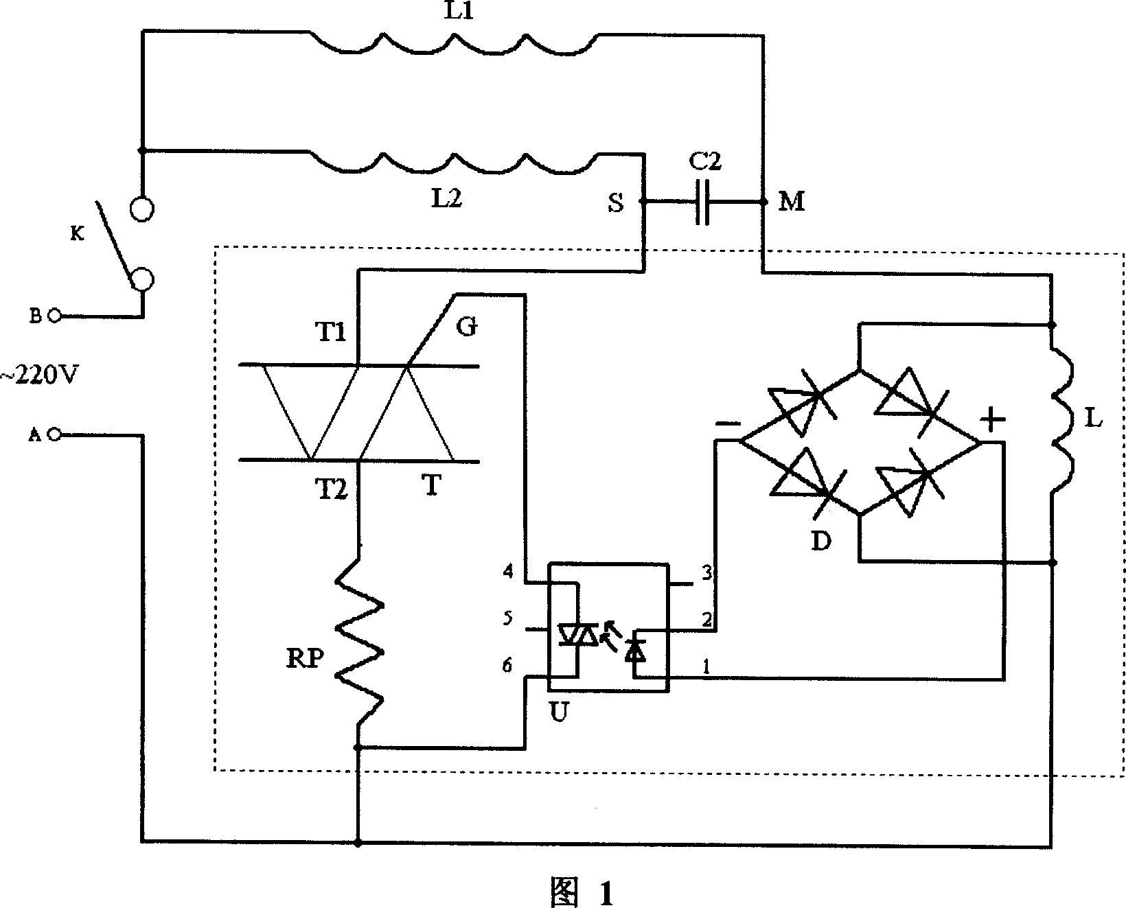
Figure 1 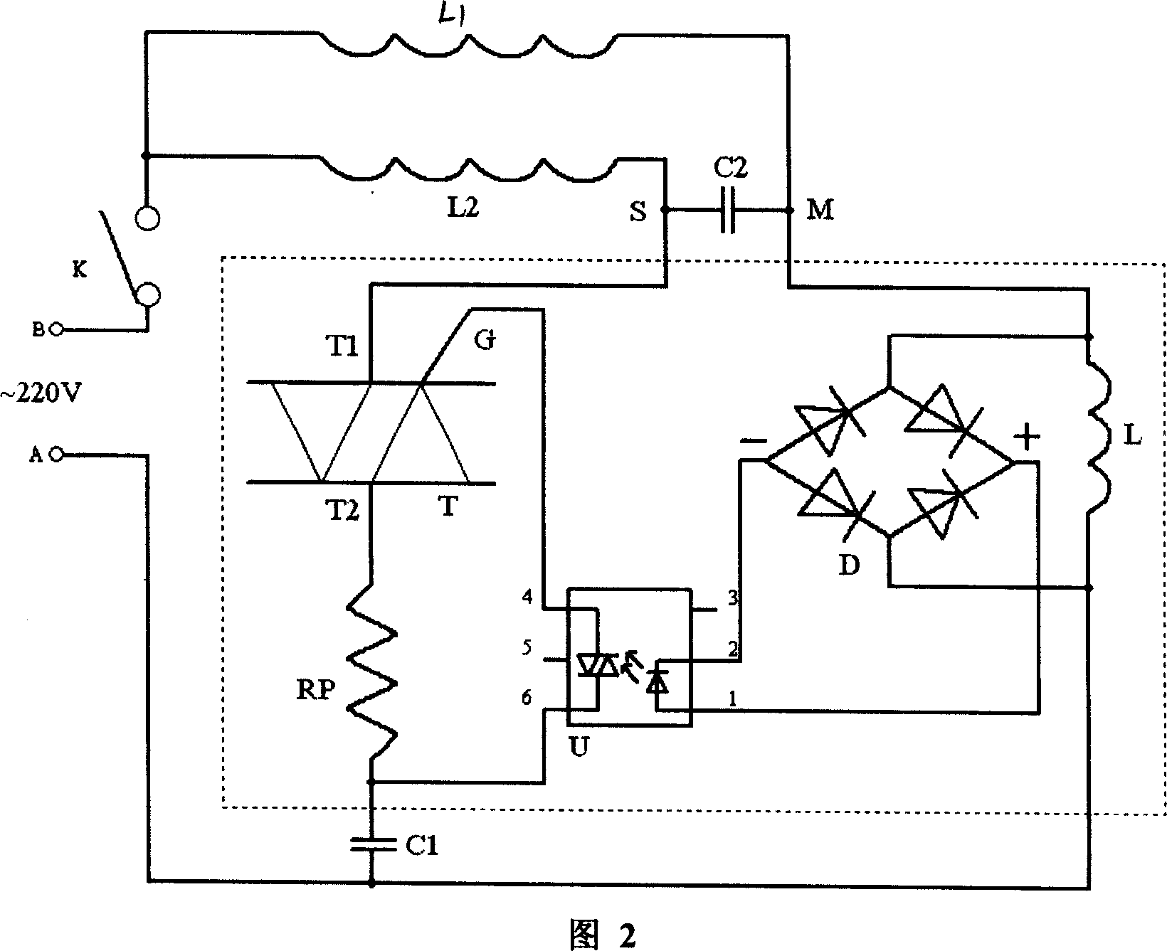
Figure 2 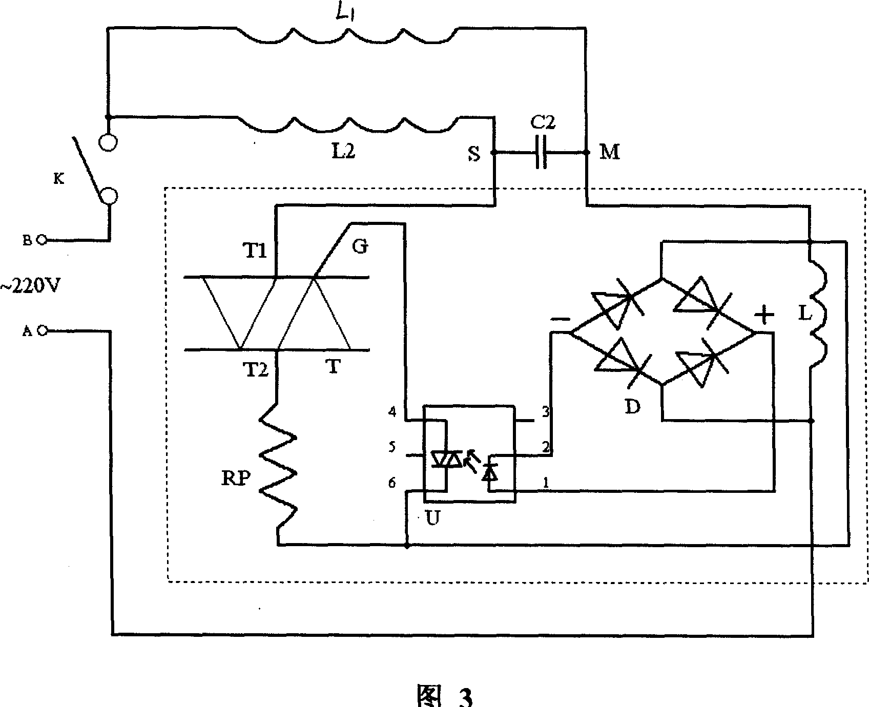
Figure 3
Abstract
Description
Technical field
[0001] The invention relates to a starter, in particular to a non-contact energy-saving starter for a single-phase AC induction motor. Background technique
[0002] A single-phase AC induction motor is generally composed of a stator and a rotor. The stator is composed of a main coil L1 and an auxiliary coil L2. The auxiliary coil L2 mainly works when the motor starts, and the main coil L1 works when the motor is running in a steady state. For any motor to run normally, it needs a good starting process. For the starting of a single-phase AC induction motor, it is necessary to connect a starter similar to a switch in series in the secondary coil circuit; it is required to be connected when the motor starts. The secondary coil L2 loop should be disconnected in time after the motor is started. A conventional motor starter is usually just a PTC thermistor with a positive temperature coefficient characteristic. If the power is turned on to the motor, a large curr...
Examples
Embodiment Construction
[0019] Shown in the dotted line box in the figure is a DC isolation control type non-contact energy-saving starter. The present invention will be further described below in conjunction with the accompanying drawings and embodiments.
[0020] Referring to Fig. 1, the first embodiment of non-contact energy-saving starter, one electrode of PTC thermistor Rp and one output end (the 6th pin) of photoelectric coupler U are connected with AC power supply end A, PTC thermistor The other electrode of the device Rp is connected to the T2 pole of the triac T, and the other output terminal (pin 4) of the photocoupler U is connected to the G pole of the control terminal of the triac T. The T1 pole of the bidirectional thyristor T and one end of the run capacitor C2 are connected to the S end of the secondary coil L2 of the motor. One end of the inductor L, an AC input end of the rectifier bridge D, and the other end of the running capacitor C2 are connected to the M end of the main coil L1...