
Method for operating a fuel pump
A fuel pump and fuel technology, which is applied to fuel injection control, electrical control, machine/engine, etc., can solve problems such as excessive switching loss, increase in temperature of switching electronic equipment, and decrease in service life of switching electronic equipment, etc., to save points and adjust effect of the device
Patent Information
- Authority / Receiving Office
- CN · China
- Patent Type
- Patents(China)
- Current Assignee / Owner
- Publication Date
- 2012-07-04
Smart Images
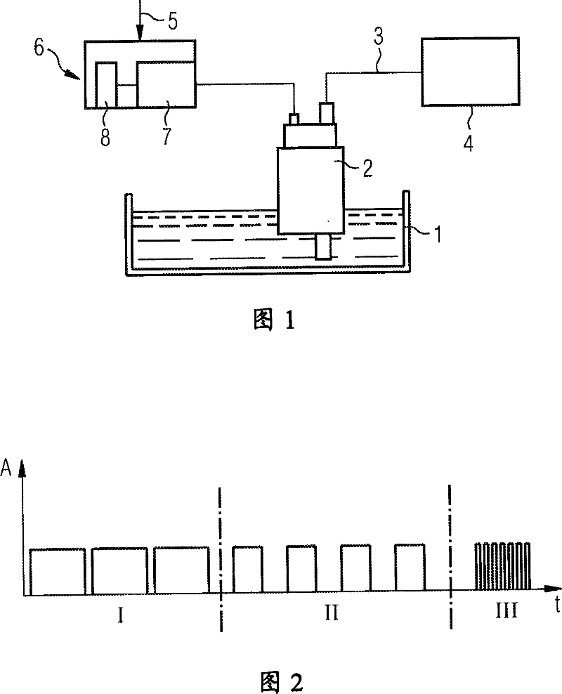
Figure 1 
Figure 2
Abstract
Description
technical field
[0001] The invention relates to a method for operating a fuel pump such that fuel is delivered from a fuel tank to an internal combustion engine, wherein pulsed electrical energy is supplied to the fuel pump and the duty cycle is adjusted in dependence on the fuel demand of the internal combustion engine. Such adjustable fuel pumps are installed, in particular, in the fuel tank of a motor vehicle. Background technique
[0002] A fuel tank which is electronically regulated according to the fuel requirement is known from DE 43 02 383 A1. Here, electrical energy is pulsed to the fuel pump, wherein the duty cycle is changed as a direct function of the regulated output signal of the air mass sensor, wherein the sensor generates a signal as a function of the position of the throttle valve, which The position is the standard for the fuel requirements of internal combustion engines. This method of regulated, pulsed supply of electrical energy is also known as pulse...
Examples
Embodiment Construction
[0020] FIG. 1 shows a schematic diagram of a fuel tank 1 of a motor vehicle, not shown further. A fuel pump 2 is arranged in the fuel tank 1 and delivers fuel from the fuel tank 1 to an internal combustion engine 4 of the motor vehicle via a feed line 3 . An electronic signal 5 obtained in a known manner is transmitted to the control electronics 6 for the fuel pump 2 , which is a criterion for the momentary fuel demand on the internal combustion engine 4 . Control electronics 6 includes a pulse generator 7 , which supplies the current for fuel pump 2 to fuel pump 2 in the form of pulses. The pulses are delivered with a constant amplitude, the pulse width being the criterion for the electrical energy delivered. The electronic control signal 6 is arranged in the shown figure outside the fuel tank 1 , for example as a component of the engine control unit. However, it is also conceivable to arrange the control electronics 6 on or in the fuel tank 1 , for example on a flange or i...