
Intelligent straw gasification furnace
A gasification furnace, intelligent technology, applied in the field of gasification furnaces, can solve the problems of inability to grasp the timing of its feeding, failure to produce gas by pyrolysis, and high moisture content of straw, so as to improve the gas production effect, reduce the failure rate, and improve The effect of gasification effect
Patent Information
- Authority / Receiving Office
- CN · China
- Patent Type
- Applications(China)
- Current Assignee / Owner
- Publication Date
- 2010-02-10
- Estimated Expiration
- Not applicable · inactive patent
Smart Images
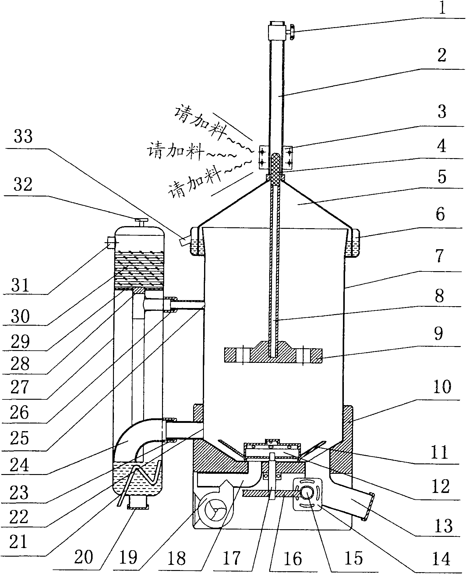
Figure 1 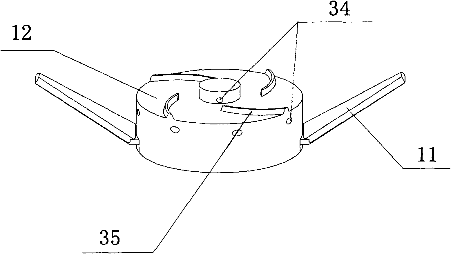
Figure 2
Abstract
Description
Technical field
[0001] The invention relates to a gasifier for converting agricultural waste into combustible gas through oxygen-limited combustion pyrolysis reaction. Especially updraft domestic gasifiers. Background technique
[0002] At present, the updraft gasifier in the prior art is simple in structure, low in cost, and has a wide range of straw resources, and because of the global concern about the energy crisis and the air pollution caused by seasonal burning of straw and other agricultural waste, the party The country and the country attach great importance to the development and utilization of this renewable energy, encourage and advocate straw energy, and strive to achieve both energy saving and environmental protection. However, due to the high requirements on the dryness of the straw in the gasifier in the prior art, the material is often removed and the flame is turned off due to the inability to grasp the timing of feeding during use, and the tar is not handl...
Examples
Embodiment Construction
[0013] exist figure 1 Among them, the upper part of the cylindrical furnace body (7) is provided with a conical dehumidification furnace cover (5) with a small upper part and a larger lower part with a certain slope, and its bottom periphery is inserted into an annular water tank (6) arranged around the furnace mouth. An overflow pipe (33) is installed on one side of the annular water tank, and a slightly thicker guide sleeve (2) is arranged upwards in the center of the humidity exhaust furnace cover (5), which can also be used as an exhaust pipe, and an exhaust valve (1) can be arranged on the upper part The lower part can fix the prompter (3) of the built-in magnetic field control switch according to the height set as required, and the guide sleeve is built with a thinner guide post (8) connected to the pressing block (9), and its top is embedded with the magnetic block (4). There should be a gap between the guide sleeve and the guide column to facilitate exhaust. The lower ...