
Self-starting equipment of vertical axis wind turbine
A self-starting, wind turbine technology, applied to wind engines, wind engines at right angles to the wind direction, machines/engines, etc., can solve the problems of reducing wind energy utilization efficiency and poor self-starting performance, and achieve the effect of improving wind energy utilization efficiency
Patent Information
- Authority / Receiving Office
- CN · China
- Patent Type
- Applications(China)
- Current Assignee / Owner
- Publication Date
- 2011-01-12
Smart Images
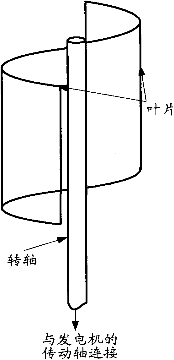
Figure 1 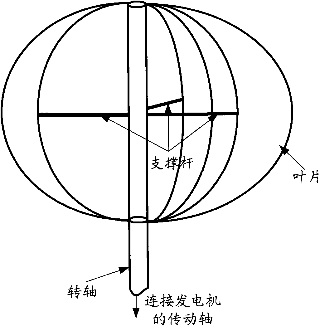
Figure 2 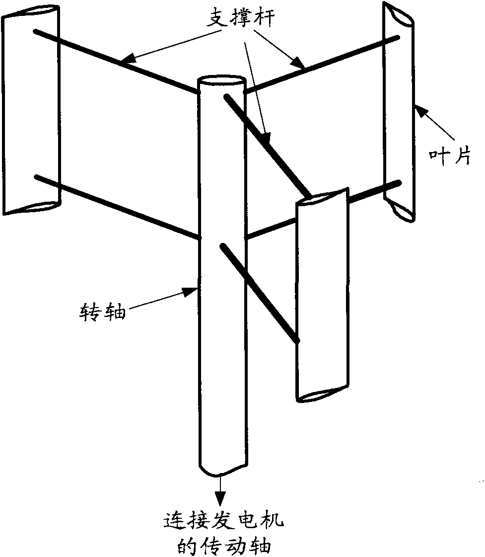
Figure 3
Abstract
Description
technical field
[0001] The invention relates to the field of wind energy applications, in particular to a self-starting device for a vertical axis wind turbine. Background technique
[0002] At present, the widely used vertical axis wind turbine mainly has three different structures, which are S-type structure, Φ-type structure and H-type structure. Among them, S-type vertical-axis wind turbines mainly use aerodynamic resistance to do work, which is called drag-type wind turbines; Φ-type and H-type vertical-axis wind turbines mainly use aerodynamic lift generated by airfoils to do work, called lift-type wind turbines .
[0003] see figure 1 , figure 1 It is a structural schematic diagram of an existing S-type vertical axis wind turbine. Among them, the S-type vertical axis wind turbine is composed of two semi-cylindrical blades and a rotating shaft, wherein the lower end of the rotating shaft is connected to the drive shaft of the generator to realize torque transmission...
Examples
Embodiment 1
[0040] see Figure 4 , Figure 4 It is a schematic structural diagram of a self-starting device for a vertical axis wind turbine provided in Embodiment 1 of the present invention. like Figure 4 As shown, the self-starting device may include:
[0041] A rotating shaft (1), a blade (2) and a support rod (3);
[0042] Wherein, the blade (2) is a straight blade; the cross-section of the support rod (3) is in the shape of a concave front and a pointed rear;
[0043] Wherein, the number of blades (2) is at least two, and at least one support rod (3) is connected between each blade (2) and the rotating shaft (1);
[0044] Wherein, the lower end of the rotating shaft (1) is connected to the transmission shaft of the generator to realize torque transmission and wind energy conversion.
[0045] In Embodiment 1 of the present invention, the blade (2) may be a whole blade, or may be formed by connecting multiple blades.
[0046] In Embodiment 1 of the present invention, each suppor...
Embodiment 2
[0056] see Figure 7 , Figure 7 It is a structural schematic diagram of another self-starting device for a vertical axis wind turbine provided in Embodiment 2 of the present invention. like Figure 7 As shown, the self-starting device may include:
[0057] A rotating shaft (1), a blade (2) and a support rod (3);
[0058] Wherein, the blade (2) is in the shape of a crescent moon; the cross section of the support rod (3) is in the shape of a concave front and a pointed rear;
[0059] Wherein, both ends of each blade (2) are fixedly connected to the rotating shaft (1), and at least one support rod (3) is connected between the inner edge of each blade (2) and the rotating shaft (1);
[0060] Wherein, the lower end of the rotating shaft (1) is connected to the transmission shaft of the generator to realize torque transmission and wind energy conversion.
[0061] In the second embodiment of the present invention, the blade (2) may be a whole piece of curved blade, or may be a ...