
Side surface support lifting device on yarn winding machine
A lifting device and winding machine technology, which is applied in the directions of transportation and packaging, transportation of filamentous materials, and thin material processing, can solve the problems of inflexible lifting, unstable contact pressure, and large vibration, and achieve smooth operation and contact Stable pressure and little vibration
Patent Information
- Authority / Receiving Office
- CN · China
- Patent Type
- Patents(China)
- Current Assignee / Owner
- Publication Date
- 2014-08-13
Smart Images
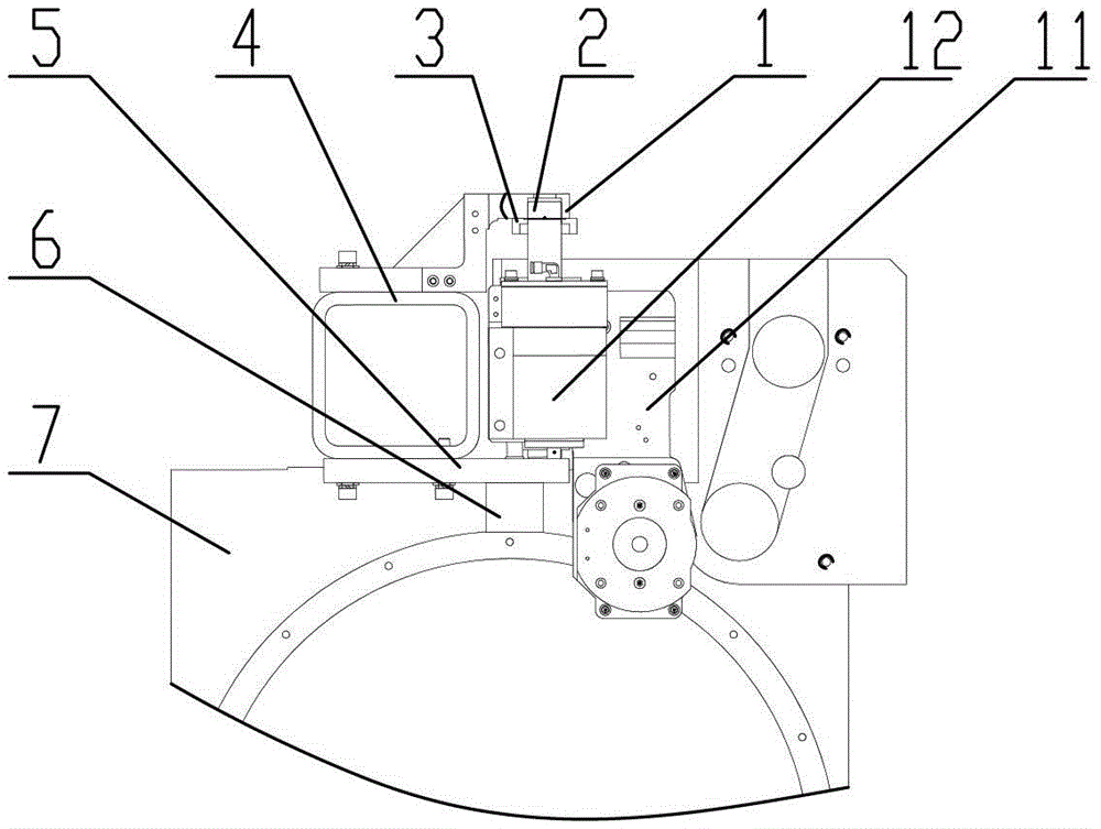
Figure 1 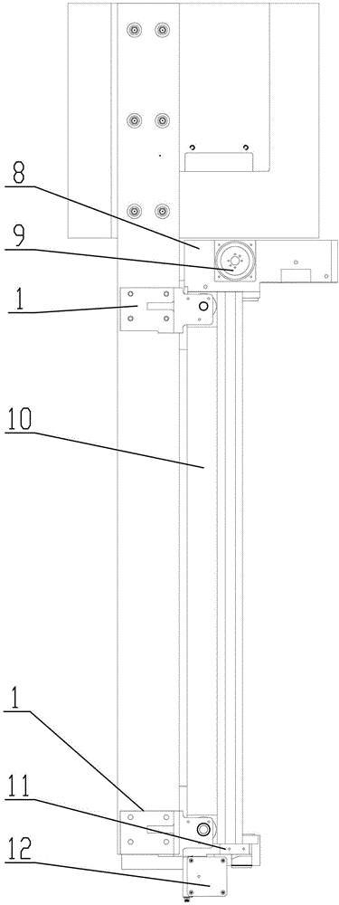
Figure 2
Abstract
Description
technical field
[0001] The invention relates to the technical field of chemical fiber machinery manufacturing, in particular to a side support lifting device on a yarn winding machine. Background technique
[0002] At present, most domestic winding machine manufacturers use the lifting support point (the center connection line of the two steel ball guide columns) and the end surface support lifting device perpendicular to the axis of the spindle shaft. With the continuous development of the technical level of the winding machine, in order to In order to improve the requirements of energy saving and consumption reduction, as well as the increase of output, the spindle shaft is getting longer and longer (the longest has reached 1800mm), resulting in the distance between the lifting support point (the center line connecting the two steel ball guide pillars) and the outer end surface of the winding machine. The longer the cantilever is, the bigger the cantilever is, and the weig...
Examples
Embodiment Construction
[0022] The present invention will be described in detail below in conjunction with the accompanying drawings.
[0023] see figure 1 and figure 2 In this embodiment, a side support lifting device on a yarn winding machine is provided. The main components involved in this embodiment include an upper positioning plate 1, a steel ball guide post 2, a rubber ring 3, a supporting square tube 4, a lower Positioning plate 5, jacking cylinder 6, machine base 7, lifting seat 8, rear lifting cylinder 9, friction roller casing 10, friction roller front box plate 11, front lifting cylinder 12.
[0024] The support square tube 4 is installed on the support 7, and the weight of the lifting device all bears on the support square tube 4.
[0025] Above the supporting square tube 4, one upper positioning plate 1 is provided at the front and rear, and one lower positioning plate 5 is respectively provided at the front and rear of the supporting square tube 4, and each pair of upper positionin...