
Ultra wide band filter based on short circuit branches
An ultra-wideband filter and short-circuit branch technology, applied in waveguide-type devices, circuits, electrical components, etc., can solve the problems of inability to make broadband, steep suppression, poor return loss, etc., and achieve the effect of out-of-band suppression of steepness
Patent Information
- Authority / Receiving Office
- CN · China
- Patent Type
- Applications(China)
- Current Assignee / Owner
- Publication Date
- 2013-09-18
- Estimated Expiration
- Not applicable · inactive patent
Smart Images
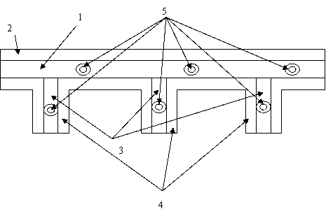
Figure 1 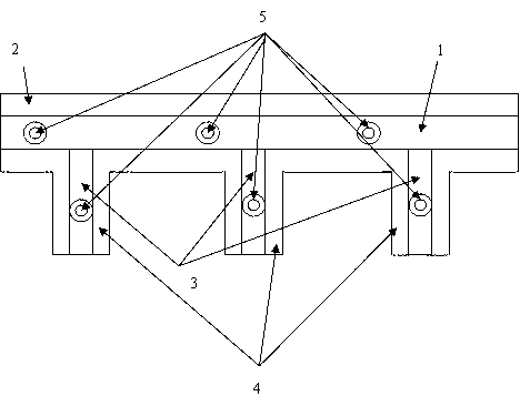
Figure 2
Abstract
Description
technical field
[0001] The invention relates to an ultra-wideband filter based on short-circuit stubs, in particular to an ultra-wide-band filter composed of strip lines and short-circuit stubs. The filter becomes a wideband bandpass filter. Background technique
[0002] A strip line short-circuit stub filter can form a wide-band high-pass filter when the length center frequency of the short-circuit stub is 1 / 4 waveguide wavelength, and the distance between adjacent short-circuit stubs is 1 / 2 waveguide wavelength. The high-end return loss of the traditional stripline short-circuit stub high-pass filter is relatively poor. This stripline short-circuit stub type cannot make a broadband bandpass filter, making its suppression very steep. In the present invention, a broadband band-pass filter is made by using interleaving screws, so that the parasitic pass-band is relatively far away, and the out-of-band suppression is very steep. Contents of the invention
[0003] The objec...
Examples
Embodiment
[0017] Such as figure 1 , 2 As shown, a short-circuit stub-based ultra-wideband filter includes a transmission line and at least two short-circuit stubs connected to the transmission line. The transmission line is mainly composed of a transmission line outer conductor 2 and a transmission line inner conductor arranged inside the transmission line outer conductor 2 1; the short-circuit stub is mainly composed of a resonant cavity 4 and a metal column 3 arranged inside the resonant cavity 4; the resonant cavity 4 is placed along one or both sides of the transmission line outer conductor 2 and connected to the transmission line outer conductor 2 One end of the metal column 4 is connected with the end of the resonance cavity 4 away from the transmission line outer conductor 2, and the other end is connected with the transmission line inner conductor 1; the upper surface and the lower surface of the transmission line outer conductor 2 are all along the transmission line outer condu...