
Self-heating staggered-arrangement micro-boss array type alcohol reforming device
A technology of micro-bosses and reformers, applied in chemical instruments and methods, inorganic chemistry, non-metallic elements, etc., can solve the problems of low efficiency, high manufacturing cost of reaction carriers, etc., to overcome large volume, realize self-heating operation, The effect of improving heat and mass transfer efficiency
Patent Information
- Authority / Receiving Office
- CN · China
- Patent Type
- Applications(China)
- Current Assignee / Owner
- Publication Date
- 2014-02-26
- Estimated Expiration
- Not applicable · inactive patent
Smart Images
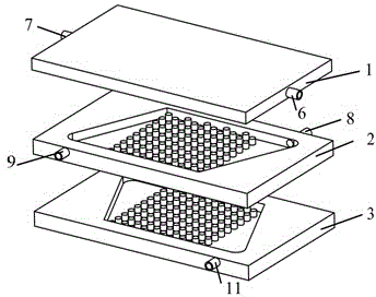
Figure 1 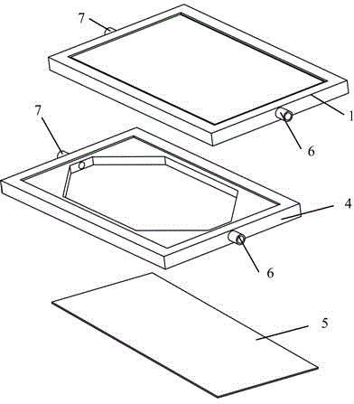
Figure 2 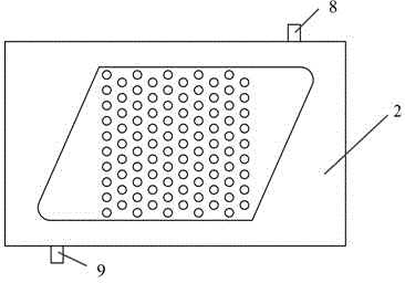
Figure 3
Abstract
Description
technical field
[0001] The invention relates to a self-heating type alcohol reformer, in particular to a self-heating staggered micro-protrusion platform array type alcohol reformer. technical background
[0002] Hydrogen energy has the advantages of high fuel calorific value, clean and environmentally friendly, and has attracted widespread attention. Among them, hydrogen fuel cells have achieved rapid development in recent years due to their high efficiency and high power density. With the vigorous development of hydrogen fuel cells, the issue of hydrogen supply for fuel cells has become a research hotspot. In the way of fuel cell hydrogen supply, an effective way is to use high-energy-density liquid fuels, especially low-carbon alcohols (such as methanol) to generate hydrogen through on-site reforming of the hydrogen production reaction system.
[0003] At present, there are three main methods of hydrogen production from alcohol reforming: steam reforming, partial oxidat...
Examples
Embodiment Construction
[0030] The present invention will be further described below in conjunction with drawings and embodiments.
[0031] Such as figure 1 As shown, the present invention consists of a hydrogen purification component 1, a reforming hydrogen production plate 2 and a catalytic combustion plate 3 from top to bottom.
[0032] Such as figure 2 As shown, the hydrogen purification unit 1 is a rectangular structure as a whole, including the hydrogen purification plate 4 and the hydrogen permeable membrane 5; The sides are all trapezoidal, and the lower bottom and short side of the two trapezoids have the same size. The two short sides of the hydrogen purification plate 4 are respectively provided with a carrier gas inlet hole and a carrier gas outlet hole. One side of the carrier gas inlet hole and the carrier gas outlet hole The other side of the carrier gas inlet hole and the carrier gas outlet hole communicates with the carrier gas inlet pipe 6 and the carrier gas outlet pipe 7 respec...