
Rotary flow guiding device
A technology of diversion device and rotary connection, which is applied in the direction of pipe components, etc., and can solve the problems that the catheter and the working device cannot rotate relative to each other and cannot meet the operation requirements
Patent Information
- Authority / Receiving Office
- CN · China
- Patent Type
- Applications(China)
- Current Assignee / Owner
- Publication Date
- 2014-09-17
- Estimated Expiration
- Not applicable · inactive patent
Smart Images
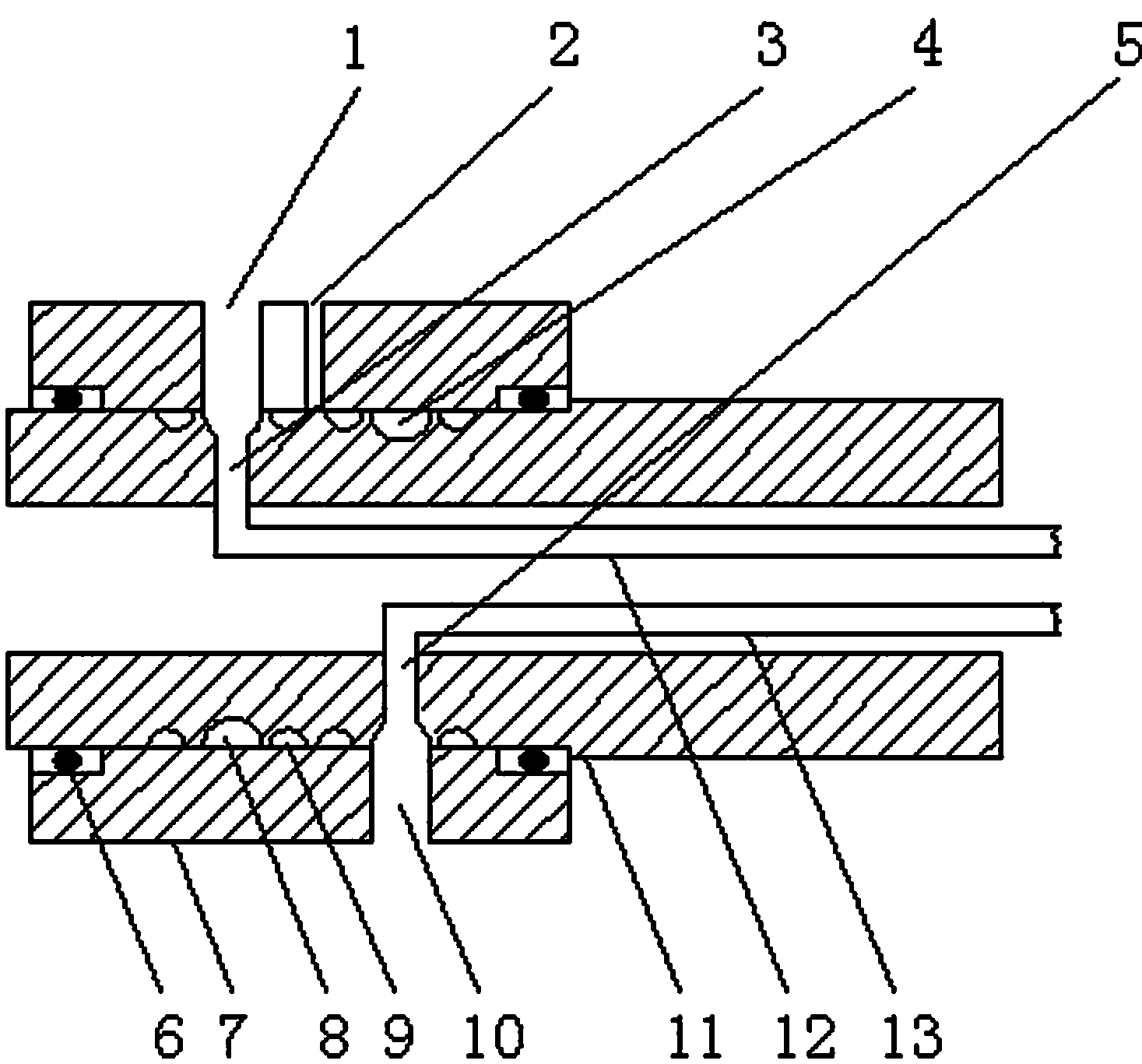
Figure 1
Abstract
Description
technical field
[0001] The invention relates to a rotary flow guide device, which is mainly used for flow guide of flowing liquid. Background technique
[0002] In production and application, the flowing liquid is fixedly connected to the working device of the required liquid through the conduit. When the liquid completes its mission, it is directly discharged from the working device; The flowing liquid is introduced into a relatively rotating working device, and when the liquid needs to be discharged from the relatively rotating working device after the liquid completes its mission, this specific operation requirement cannot be met. Contents of the invention
[0003] The technical problem to be solved by the present invention is to provide a rotary flow guiding device capable of introducing and exporting liquid during rotation.
[0004] The present invention is accomplished in this way. A rotary flow guide device includes a shaft sleeve and a hollow shaft. The hollow sha...
Examples
Embodiment Construction
[0009] The present invention is further described in detail in conjunction with the accompanying drawings. A rotary flow guide device includes a shaft sleeve 7 and a hollow shaft 11. The hollow shaft 11 is rotationally connected with the shaft sleeve 7 through a bearing 6. The water inlet provided on the shaft sleeve 7 The hole 1 and the water outlet hole 10 communicate with the water inlet annular groove 8 and the water outlet annular groove 4 respectively on the hollow shaft 11, and the upper and lower sides of the water inlet annular groove 8 and the water outlet annular groove 4 are provided with sealing rings 9. The water inlet annular groove 8 and the water outlet annular groove 4 communicate with the water inlet connecting pipe 12 and the water outlet connecting pipe 13 respectively arranged in the hollow shaft 11 .
[0010] In order to ensure that the hollow shaft 11 can run normally, an oil filling hole 2 is provided on the bearing sleeve.
[0011] In order to ensure ...