
A gynecological loop taker
A ring taker and gynecological technology, applied in the field of medical devices, can solve the problems of low work efficiency, low one-time success rate, complicated ring taking process, etc., and achieve the effects of improving work efficiency, high success rate, and simple and convenient operation.
Patent Information
- Authority / Receiving Office
- CN · China
- Patent Type
- Patents(China)
- Current Assignee / Owner
- Publication Date
- 2017-01-25
- Estimated Expiration
- Not applicable · inactive patent
Smart Images
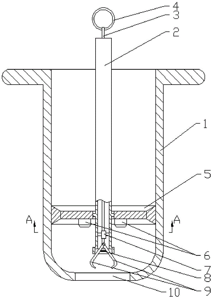
Figure 1 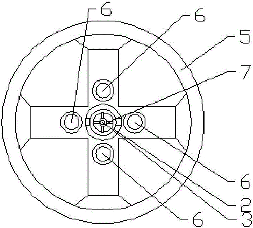
Figure 2
Abstract
Description
technical field
[0001] The invention relates to a medical device, in particular to a gynecological ring remover. Background technique
[0002] At present, the contraceptive methods for married women of childbearing age in my country mainly include instrumental contraception, drug contraception, and natural contraception, among which the intrauterine device (IUD) is a relatively safe, convenient and extensive contraceptive method. The intrauterine device is a ring (also known as contraceptive ring, birth control ring) made of stainless steel, plastic, or silicone rubber. Its role is mainly to resist fertilization and prevent the implantation of fertilized eggs. , so as to achieve the purpose of contraception. It is effective for a long time after being placed, and can be taken out when pregnancy is required without affecting fertility. Clinically, the contraceptive ring needs to be taken out with a ring hook, which is inserted into the uterus through the cervix, and the con...
Examples
Embodiment
[0025] Example: such as figure 1 and figure 2 As shown, a gynecological ring remover includes a cylindrical housing 1, one end of the housing 1 is provided with a flange, the other end is in a hemispherical structure, and a ring removal hole 10 is provided in the middle. A hollow support rod 2 is provided;
[0026] The support rod 2 is provided with a pull rod 3;
[0027] One end of the pull rod 3 located outside the support rod 2 is provided with a pull ring 4;
[0028] The other end of the pull rod 3 is provided with two ring-taking hooks 9;
[0029] One end of the two ring hooks 9 is hinged to the end of the pull rod 3;
[0030] A compression spring 8 is arranged in the middle of the two ring-taking hooks 9;
[0031] The inner wall of the support rod 2 is provided with a first support frame 7;
[0032] The pull rod 3 passes through the first support frame 7 .
[0033] The inner wall of the housing 1 is slidably provided with a second support frame 5, and the support...