
Pneumatic clamp for clamping motorcycle engine to carry out power measurement
A technology for motorcycles and engines, applied in manufacturing tools, workpiece clamping devices, etc., can solve the problems of engine consistent production that cannot meet requirements, poor engine reliability, inconsistent test results, etc., and achieves easy and reliable disassembly and assembly of engines. Good performance and clear lines
Patent Information
- Authority / Receiving Office
- CN · China
- Patent Type
- Applications(China)
- Current Assignee / Owner
- Publication Date
- 2015-04-01
- Estimated Expiration
- Not applicable · inactive patent
Smart Images
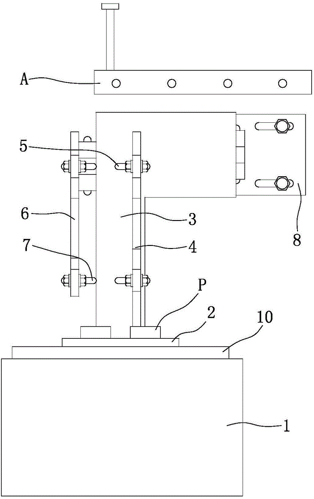
Figure 1 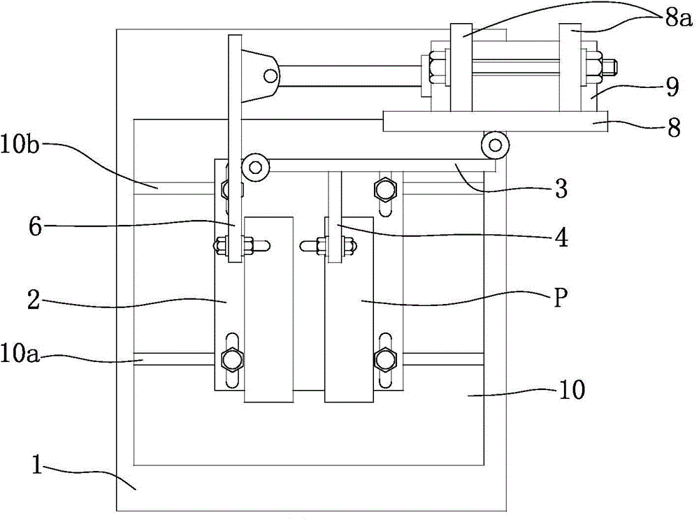
Figure 2 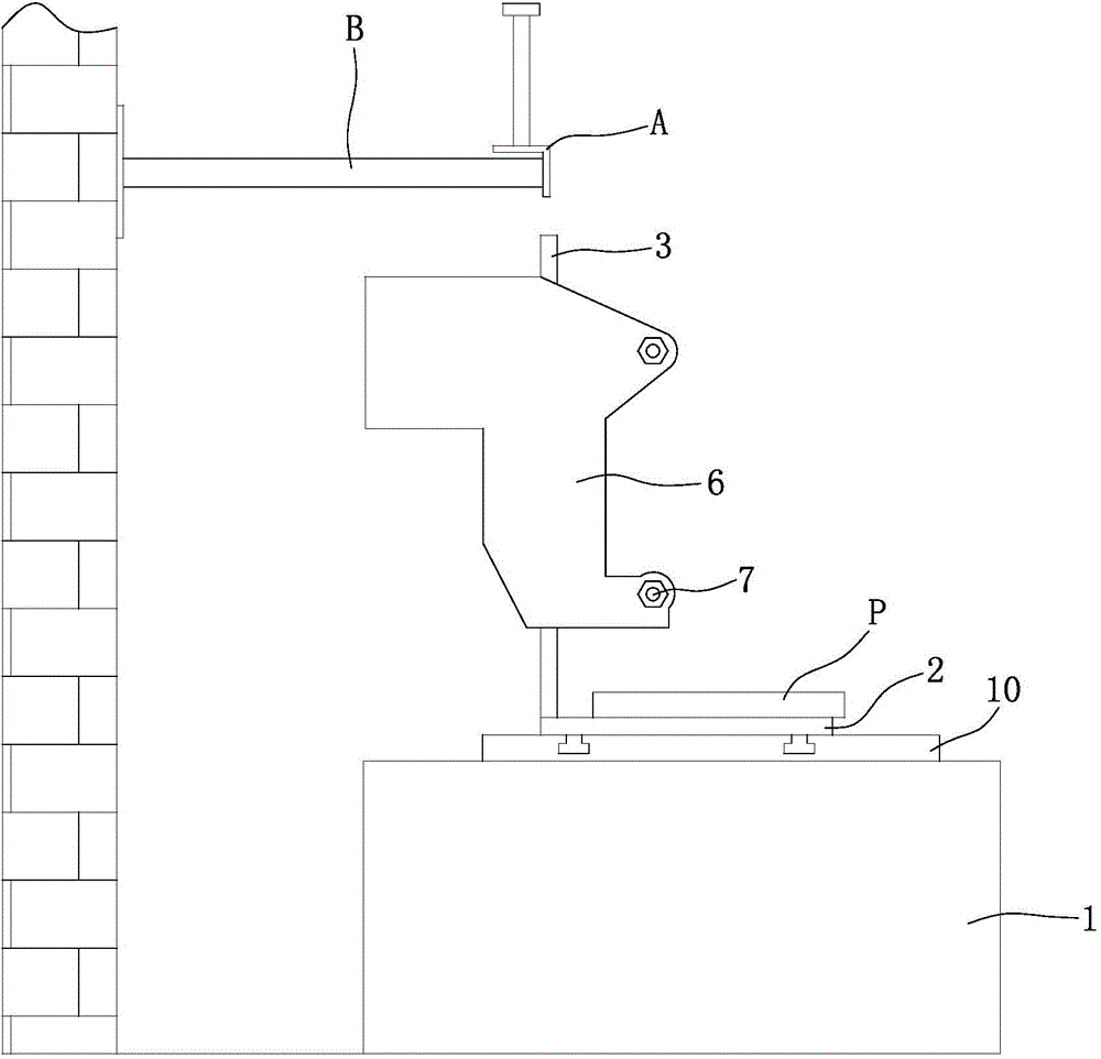
Figure 3
Abstract
Description
technical field
[0001] The invention belongs to the technical field of motorcycle engines, and in particular relates to a test fixture for motorcycle engines. Background technique
[0002] After the motorcycle engine is assembled, it needs to be tested on the bench to verify whether the performance of the engine meets the requirements. The existing engine performance test bench is not only complex in structure and takes up a lot of space, but also the operation of installing the engine on the bench is very cumbersome, time-consuming and laborious, and the labor intensity of workers is high, which will greatly affect the efficiency of the test. At the same time, the reliability of the positioning of the engine on the bench is poor, which will cause the test results to be inconsistent with the real situation, so that the consistent production of the engine is difficult to meet the requirements. Contents of the invention
[0003] The technical problem to be solved by the pre...
Examples
Embodiment Construction
[0021] Below in conjunction with accompanying drawing and embodiment the present invention will be further described:
[0022] Such as figure 1 , figure 2 , image 3 As shown, the base 1 is a cuboid and fixed on the ground. The backing plate 10 is fixedly installed on the top surface of the base 1, the backing plate 10 is a rectangular steel plate, and the front transverse groove 10a and the rear transverse groove 10b parallel to each other are provided on the backing plate 10, and each transverse groove starts from the left end of the backing plate 10. Pass through to the right. A bottom plate 2 is arranged on the backing plate 10 , the bottom plate 2 is preferably a rectangular steel plate, and the bottom surface of the bottom plate 2 is attached to the top surface of the backing plate 10 . The bottom plate 2 is connected to the backing plate 10 through two front bolts and two rear bolts. The four bolts are distributed in a rectangle, and the lower ends of the front bol...