
Rotating device energy absorption protection device
A technology for rotating equipment and protective devices, applied in the direction of non-rotating vibration suppression, springs, etc., can solve problems affecting the stable operation of rotating equipment, and achieve the effects of simple structure, reduced torsion angle and beating, and convenient maintenance
Patent Information
- Authority / Receiving Office
- CN · China
- Patent Type
- Applications(China)
- Current Assignee / Owner
- Publication Date
- 2015-06-24
Smart Images
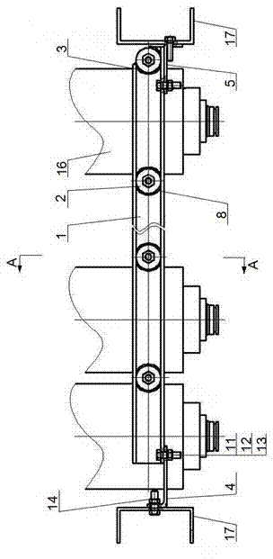
Figure 1 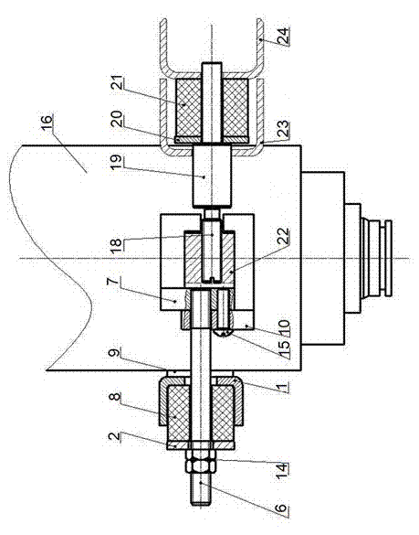
Figure 2 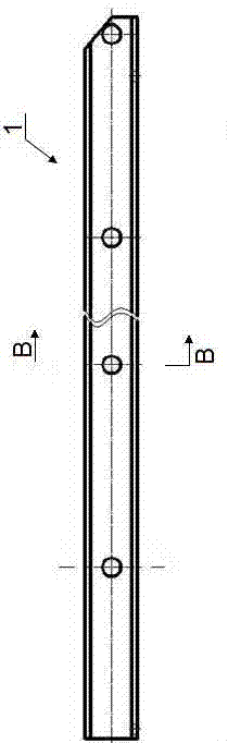
Figure 3
Abstract
Description
technical field
[0001] The invention belongs to an energy-absorbing protection device, in particular to an energy-absorbing protection device for rotating equipment. Background technique
[0002] When operating multiple rotating equipment at the same time, failure phenomena such as damage to a single equipment will inevitably occur, and the linear speed of the failed single equipment will increase significantly, and the energy released will also increase accordingly. There is a set of protection device in the bracket, its main function is to absorb the failure energy through the protection device when a single device fails, and protect the normal operation of other machines in the rack. However, in the process of development, it was found that the energy released by the failed single equipment exceeded the design capacity of the original protection device, and the failure of a single equipment would affect the stable operation of other rotating equipment mounted on the rack....
Examples
Embodiment Construction
[0043] Below, the present invention is described in detail with reference to accompanying drawing and embodiment:
[0044] like figure 1 , 2 As shown, an energy-absorbing protection device for rotating equipment includes an auxiliary horizontal bar 1, and the auxiliary horizontal bar 1 is horizontally connected in series with a plurality of rotating equipment 16 (ten in this practical model), and the left and right ends of the auxiliary horizontal bar 1 pass through tight Solid bolt 11, washer 12, fastening nut 13 are respectively fixed with the bottom surface of left fixed angle 4 and the bottom surface of right fixed angle 5, and the side of left fixed angle 4 and the side of right fixed angle 5 are respectively fixed with support 17. A special-shaped rubber spring 3 is arranged between the right end of the auxiliary horizontal bar 1 and the auxiliary pressure pad 2 .
[0045] The upper hook 7 and the lower hook 10 are fastened together. One end of the pull rod 6 passes t...