
Road Grooving Machine
A technology of grooving machine and cutting wheel, which is applied to roads, roads, road repair and other directions, can solve the problems of large grooving machine body, small system pressure, large pollution, etc., to avoid personal health, improve system pressure, reduce The effect of labor intensity
Patent Information
- Authority / Receiving Office
- CN · China
- Patent Type
- Patents(China)
- Current Assignee / Owner
- Publication Date
- 2016-12-07
Smart Images
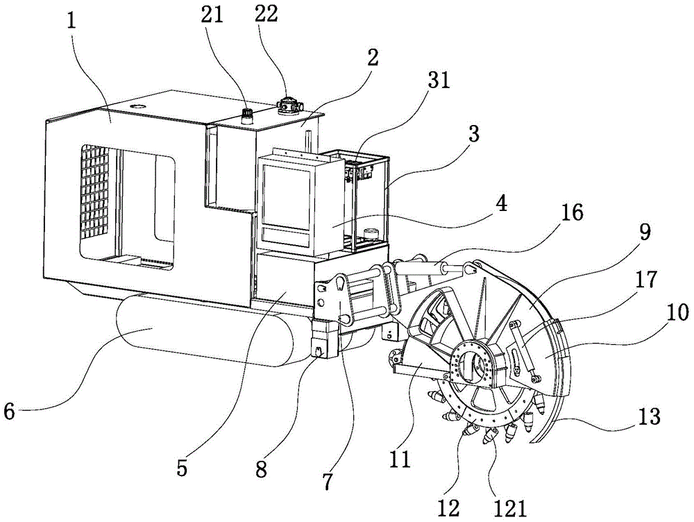
Figure 1 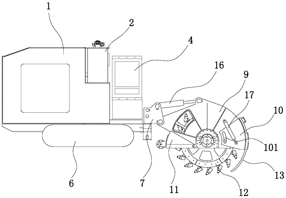
Figure 2 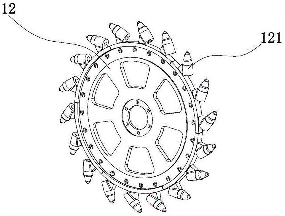
Figure 3
Abstract
Description
technical field
[0001] The invention relates to the technical field of engineering equipment, in particular to equipment for grooved road surfaces. Background technique
[0002] During the laying of cables and pipes, it is necessary to open installation grooves at the laying place, and bury the pipes and cables in the grooves. In the prior art, the grooving on the road surface is generally operated by a manual hand-held grooving device, which has the advantage of being flexible and convenient to use, but has obvious disadvantages: the grooving device is driven by a diesel engine, and the vibration is large during operation, requiring a large Hand-held force, labor intensity is high; slotting produces a lot of dust, which affects the health of workers and pollutes the environment; the depth and width of slotting are controlled by hands, and the control effect is not good, and the degree of damage to the road surface outside the slot is relatively large when slotting . [00...
Examples
Embodiment Construction
[0028] The specific implementation manner of the present invention will be described below in conjunction with the accompanying drawings.
[0029] Such as figure 1 , figure 2 As shown, the road surface grooving machine of the present embodiment includes a slotting device installed at the front end of the driving device, the driving device includes a power station cover 1, and a diesel tank 5, an electric control cabinet 4, a The control cabinet 3 and the hydraulic oil tank 2, the diesel engine and the oil pump are installed in the power station cover 1, and the crawler belt 6 is installed under the power station cover 1, and the crawler belt 6 is driven by a hydraulic motor; Cutting wheel 12, the cutting wheel 12 is driven by a hydraulic motor; the slag cleaning plate 10 positioned at the front of the cutting wheel 12 and the dust cover 11 positioned at the rear of the cutting wheel 12 are installed on the cutting wheel support 9, and the side of the cutting wheel support 9 ...