
Parallel thyristor circuit with overvoltage protection
A thyristor and overvoltage technology, which is applied in the field of parallel thyristor overvoltage protection circuit, can solve problems such as early triggering, large on-off current, and thyristor burnout, and achieve the effects of avoiding interference, improving consistency, and preventing false triggering
Patent Information
- Authority / Receiving Office
- CN · China
- Current Assignee / Owner
- Publication Date
- 2015-09-23
- Estimated Expiration
- Not applicable · inactive patent
Smart Images
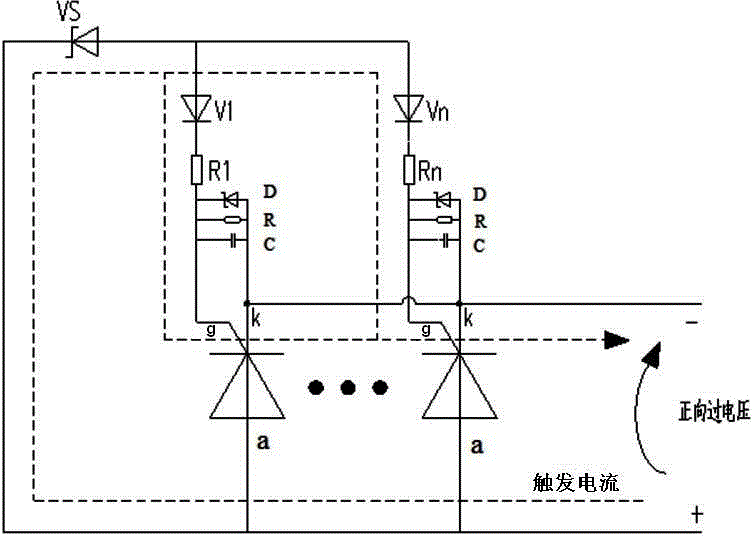
Figure 1
Abstract
Description
technical field
[0001] The invention mainly relates to the technical field of power electronics, in particular to a parallel thyristor overvoltage protection circuit. Background technique
[0002] At present, two methods are generally used for overvoltage protection of thyristor components: the first method is to use a voltage detection circuit and preset the overvoltage threshold through the control system. When the voltage across the thyristor received by the control system exceeds its When the preset threshold voltage is reached, the control system sends out a trigger signal to forcibly trigger the thyristor. But this method needs to configure the control system, and is limited by the control hardware and control program, the design is complex and difficult to maintain.
[0003] The second method is to use BOD (Break Over Diode), which is a breakdown diode as a protection device. This method is generally used in series thyristor circuits. In the series thyristor circuit...
Examples
Embodiment Construction
[0018] The present invention will be further described below in conjunction with the accompanying drawings and specific embodiments.
[0019] like figure 1 As shown, the parallel thyristor circuit with overvoltage protection in this embodiment includes a plurality of thyristors V1-Vn, and the plurality of thyristors are connected in parallel, that is, the anodes a of the plurality of thyristors are connected to each other, and the cathodes k of the plurality of thyristors are connected to each other, and the gates of the plurality of thyristors The pole g and the anode a are connected through a trigger element. Under normal circumstances, the trigger element presents high impedance, and the gate g of the thyristor has no current passing through, and the thyristor is in an off state. When applied to multiple thyristor anode a and cathode k When the positive voltage between exceeds the trigger voltage of the trigger element, the trigger element will turn to the on-state, and at ...