
Harmonic gear reducer starting torque and friction resistance torque testing system and method
A technology of gear reducer and starting torque, which is applied in the direction of machine gear/transmission mechanism test, force/torque/power measuring instrument, machine/structural component test, etc., to achieve a wide range of test applications
Patent Information
- Authority / Receiving Office
- CN · China
- Patent Type
- Patents(China)
- Current Assignee / Owner
- Publication Date
- 2018-01-05
Smart Images
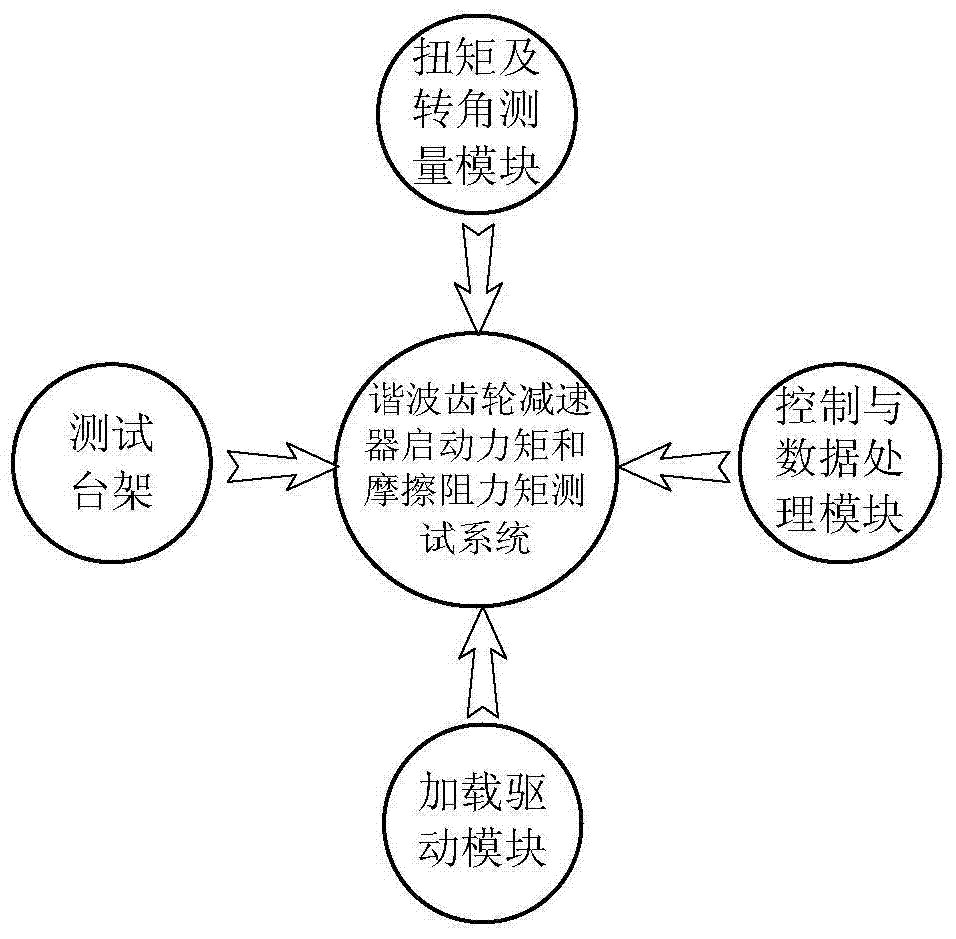
Figure 1 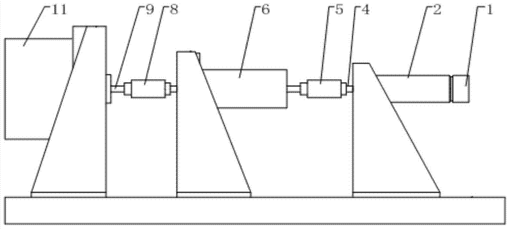
Figure 2 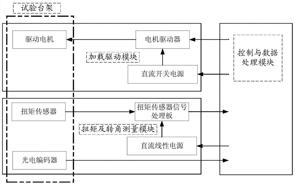
Figure 3
Abstract
Description
technical field
[0001] The invention relates to a testing system and testing method for the starting torque and friction resistance torque of a harmonic gear reducer. Background technique
[0002] Harmonic gear reducer is a kind of reducer developed by using the principle of planetary gear transmission. Harmonic gear transmission has shown its superiority since its appearance, with high transmission ratio, small backlash, high transmission precision and few parts , Easy installation, small size, light weight, high torque capacity, high efficiency, stable transmission, low noise, and can transmit motion to confined spaces. Therefore, harmonic gear reducers are increasingly widely used in aerospace, bionic machinery, precision machinery, robots and other fields.
[0003] After the precision harmonic gear reducer is processed and assembled, it is necessary to measure the starting torque and friction resistance torque to verify and evaluate the overall performance and assembly ...
Examples
Embodiment Construction
[0051] Such as figure 1 As shown, the present invention provides a starting torque and friction resistance torque testing system of a harmonic gear reducer, including: a loading drive module, a torque and rotation angle measurement module, a control and data processing module, and a test bench. Such as figure 2 As shown, the driving motor 2 is connected to the photoelectric encoder 1, the driving motor 2 is connected to the first coupling 5 through the connecting sleeve 4, the other end of the first coupling 5 is connected to the input end of the torque sensor 6, and the torque sensor 6 The test end is connected to the second coupling 8, and the measured harmonic reducer 11 is connected to the second coupling 8 through the adapter shaft 9. The measured harmonic reducer 11, the drive motor 2, and the torque sensor 6 are respectively fixed on the base on the three mounting brackets on the table.
[0052] Such as image 3 , the loading drive module includes a motor driver, a ...