
Installing and locking device used for circuit board and provided with sensors and rollers
A locking device and circuit board technology, applied in metal processing, metal processing equipment, manufacturing tools, etc., can solve the problems of increasing circuit board production costs, inconvenient centralized storage and transportation, and additional space costs
Patent Information
- Authority / Receiving Office
- CN · China
- Patent Type
- Applications(China)
- Current Assignee / Owner
- Publication Date
- 2016-05-04
- Estimated Expiration
- Not applicable · inactive patent
Smart Images
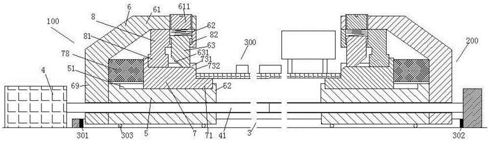
Figure 1
Abstract
Description
technical field
[0001] The invention relates to the field of circuit boards, in particular to an installation locking device for circuit boards with sensors and rollers. Background technique
[0002] The installation and removal of the circuit board will affect the operation stability and reliability of the equipment using the circuit board, and will affect its maintainability. The installation of the current circuit board often adopts the method of opening a hole on the circuit board and inserting the circuit board through the fixing column arranged on the equipment rack. Holds the circuit board in place and can be removed for maintenance during use.
[0003] However, this installation mode first needs to open a through hole on the circuit board, which will affect the wiring layout of the circuit board itself, and will also affect the stability of the wiring around the through hole. Second, such vias affect the mechanical strength of the board itself. More importantly, t...
Examples
Embodiment Construction
[0009] Combine below figure 1 The present invention will be described in detail.
[0010] According to an embodiment, an installation and locking device for a circuit board 300 with sensors and rollers includes a drive motor 4 fixedly connected to the base frame, a drive screw 41 power-coupled with the drive motor 4 , a drive screw 41 powered by the drive screw The left mounting assembly 100 and the right mounting assembly 200 are respectively driven by two sections of threads with opposite rotation directions on 41, and the guide rail member 3 that is fixedly connected with the base frame and guides the left mounting assembly 100 and the right mounting assembly 200 , wherein, the left mounting assembly 100 and the right mounting assembly 200 are arranged symmetrically from left to right, and each includes: a threaded base 5 threadedly fitted with the drive screw 41 , a fixed screw fixedly connected to the outer end of the threaded base 5 Frame 6, the mounting bearing block 7...