
A circulating sand soot blowing device
A technology of soot blowing device and sand, which is applied to the treatment of combustion products, combustion methods, and removal of solid residues, etc. It can solve problems affecting the health of workers, damage to the seal of boiler furnace walls, and influence on boiler operation, etc., to achieve soot blowing Good effect, high safety in use, and effect of improving safety in use
Patent Information
- Authority / Receiving Office
- CN · China
- Patent Type
- Patents(China)
- Current Assignee / Owner
- Publication Date
- 2017-08-25
Smart Images
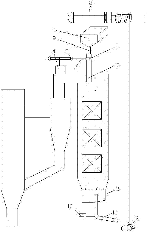
Figure 1 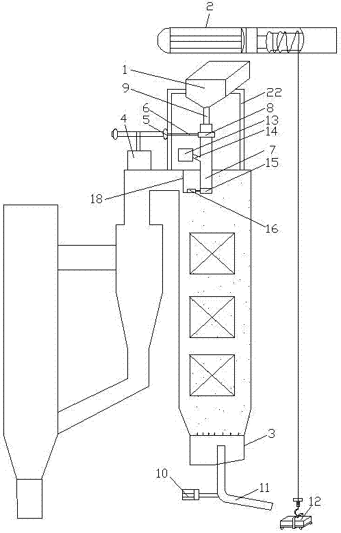
Figure 2 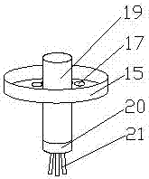
Figure 3
Abstract
Description
Technical field
[0001] The invention relates to the technical field of boiler ash removal equipment, in particular to a circulating sand soot blowing device. Background technique
[0002] The circulating fluidized bed boiler adopts a single drum, natural circulation method, and is generally divided into two vertical shafts at the front and rear. The front shaft is a total hanging structure, surrounded by membrane water walls. From bottom to top, it is the primary air chamber, dense phase area, and dilute phase area. The tail shaft adopts a supporting structure, and the two shafts are connected by a vertical cyclone separator, and the lower part of the separator is connected with a return device and an ash cooler. Both the combustion chamber and the separator are equipped with anti-wear linings, the front shaft uses a tube furnace wall, the external metal guard plate, and the tail shaft uses a light furnace wall. Eight steel columns bear the full weight of the boiler.
[0003] Ci...
Examples
Embodiment 1
[0064] See figure 1 , A circulating sand soot blowing device, comprising a sand bucket 1 and an electric hoist 2 connected to the top of the furnace, and also comprising a sandblaster connected to the top of the tail shaft and a fluidized bed 3 connected to the bottom of the tail shaft. The sander includes a speed regulating motor 4, a belt pulley 5, a transmission belt 6, a sandblasting pipe 7 and a bearing 8 connected to the sandblasting pipe 7. The sand bucket 1 is connected to the sandblasting pipe 7 through the sand inlet pipe 9, and the speed regulating motor 4 The motor shaft is in transmission connection with the pulley 5, the pulley 5 is in transmission connection with the bearing 8 through the transmission belt 6, the sandblasting pipe 7 is in communication with the tail shaft, and the fluidized bed 3 is connected with an auger driven by the motor 10 11. A sand discharge trolley 12 is connected to the electric hoist 2.
[0065] This embodiment is the most basic implemen...
Embodiment 2
[0067] See figure 2 with image 3 , A circulating sand soot blowing device, comprising a sand bucket 1 and an electric hoist 2 connected to the top of the furnace, and also comprising a sandblaster connected to the top of the tail shaft and a fluidized bed 3 connected to the bottom of the tail shaft. The sander includes a speed regulating motor 4, a belt pulley 5, a transmission belt 6, a sandblasting pipe 7 and a bearing 8 connected to the sandblasting pipe 7. The sand bucket 1 is connected to the sandblasting pipe 7 through the sand inlet pipe 9, and the speed regulating motor 4 The motor shaft is in transmission connection with the pulley 5, the pulley 5 is in transmission connection with the bearing 8 through the transmission belt 6, the sandblasting pipe 7 is in communication with the tail shaft, and the fluidized bed 3 is connected with an auger driven by the motor 10 11. A sand discharge trolley 12 is connected to the electric hoist 2.
[0068] An induced draft fan 13 is ...
Embodiment 3
[0076] See Figure 3-Figure 5 , A circulating sand soot blowing device, comprising a sand bucket 1 and an electric hoist 2 connected to the top of the furnace, and also comprising a sandblaster connected to the top of the tail shaft and a fluidized bed 3 connected to the bottom of the tail shaft. The sander includes a speed regulating motor 4, a belt pulley 5, a transmission belt 6, a sandblasting pipe 7 and a bearing 8 connected to the sandblasting pipe 7. The sand bucket 1 is connected to the sandblasting pipe 7 through the sand inlet pipe 9, and the speed regulating motor 4 The motor shaft is in transmission connection with the pulley 5, the pulley 5 is in transmission connection with the bearing 8 through the transmission belt 6, the sandblasting pipe 7 is in communication with the tail shaft, and the fluidized bed 3 is connected with an auger driven by the motor 10 11. A sand discharge trolley 12 is connected to the electric hoist 2.
[0077] An induced draft fan 13 is conne...